B1BBM2K1 - 406D9 DW10TD ENGINE DW10ATED ENGINE
ENGINE INTRODUCTION DW10
1 - DESCRIPTION
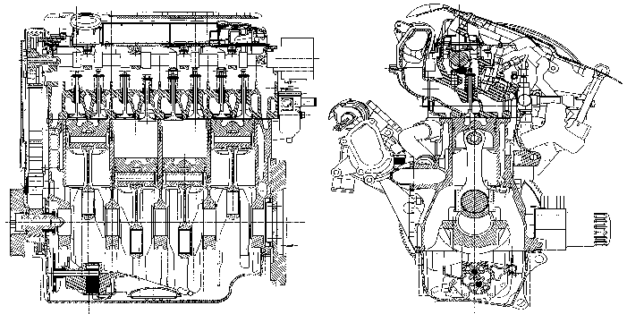
Main structure of the DW10 engine :
There are 2 versions of this engine :
The DW10 ATED engine is an improved version of the DW10TD engine, This power and torque improvement is obtained through management of the turbocharger pressures by the electronic injection ECU .
2 - IDENTIFICATION
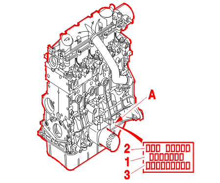
(A) Identification marking comprising :
3 - DATA
| engine type | DW10 ATED | DW10 TD |
|---|---|---|
| engine code | RHZ | RHY |
| unit reference | vehicle specific | |
| number of cylinders | 4 | |
| bore x stroke (mm) | 85 x 88 | |
| capacity (cm3) | 1996 | |
| compression ratio | 18/1 | |
| maximum power (KW - EC) | 80 | 66 |
| maximum power (HP DIN) | 110 | 90 |
| engine speed at max. power (r.p.m.) | 4000 | |
| maximum torque (da.Nm - EC) | 25 | 20.5 |
| engine speed at max. torque (r.p.m.) | 2000 | |
| turbocharger | vehicle specific | |
| air/air intercooler | yes | no |
| turbocharger pressure (2000 rpm) | 1 bar(s) | |
| turbocharger pressure (3000 rpm) | 1 bar(s) | |
| injection system | COMMON RAIL | |
| make | BOSCH | |
| type | EDC 15C2 | |
| opacity of smoke (m - 1) | specific to : vehicles | |
4 - CYLINDER BLOCK
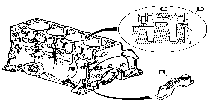
Cylinder block :
The cylinder block is identical for both the DW10 ATED and DW10TD engines and is differentiated by the engine engraving (Legislation type) .
NOTE : no. cylinder-number 1 : clutch end (flywheel) .
5 - CRANKSHAFT AND CONNECTING RODS
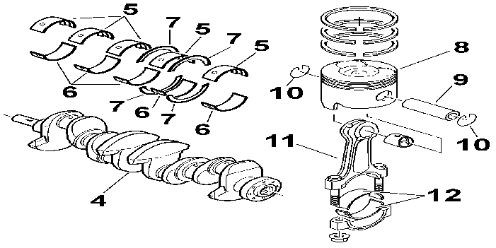
(4) Crankshaft .
(5) Top half shells .
(6) Bottom half shells .
(7) End float thrust washer .
(8) Piston .
(9) Gudgeon pin .
(10) Stop ring .
(11) Connecting rod .
(12) Big end bearing shell .
5 - 1 - CRANKSHAFT
DW10 ATED engine :
DW10 TD engine :
Front and rear sealing is by lip seals .
The end float (between 0.07 and 0.32 mm) is adjusted on bearing no. 2 by 4 thrust washers (2 on the cylinder block side and 2 on the crankshaft cap side) .
5 - 2 - CRANKSHAFT HALF SHELLS
Crankshaft half shells :
5 - 3 - CONNECTING RODS
New connecting rods (145 mm between centres) (Identical to DW8 engine) :
5 - 4 - PISTONS
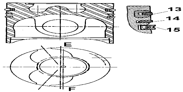
(E) : Flywheel end .
(F) : Timing gear end .
Special pistons with dome and central cavity (BOWL) necessary for the movement of the gases (SWIRL) .
New light alloy pistons with valve cut-outs .
The direction is given by the valve stamp (stamp on the side opposite the oil filter) .
There is only one piston diameter category (Series) .
There is only one piston diameter category (Repair) .
One weight category, obtained by internal reworking of the pin .
The floating gudgeon pin is retained by 2 rings .
The piston has a steel insert to reinforce the compression ring groove .
5 - 5 - PISTON RINGS
The piston has 3 rings :
5 - 6 - FLYWHEEL
Flywheel (Adapted for each vehicle) :
5 - 7 - ACCESSORIES PULLEY
A pulley for versions without air conditioning (damped hub with no torsion uncoupling step) .
A pulley for versions with air conditioning (damped hub with torsion uncoupling step) .
These pulleys are secured to the crankshaft by 1 bolt (Identical to XUD) .
6 - CYLINDER HEAD ASSEMBLY
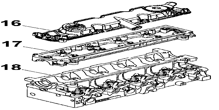
6 - 1 - CYLINDER-HEAD COVER (16)
The cylinder head cover (16) is made from a composite material, it is fitted with a pre-formed removable seal .
The oil filler hole is incorporated in the cylinder head cover .
6 - 2 - CAMSHAFT BEARING CASTING (17)
The camshaft main bearing cap housing (17) is made from a light alloy .
Cap housing/cylinder head sealing is by CAF 33 type sealing compound .
The camshaft is positioned in the cylinder head by the studded cap housing, with 5 main bearings .
The end float adjustment of the camshaft is on bearing no. 3 (Bearing no. 1 on the flywheel end) .
6 - 3 - CYLINDER HEAD (18)
A new cylinder head (18) : 2 valves per cylinder .
Height of new cylinder head : 133 mm .
Maximum cylinder head bow : 0.03 mm .
The inlet ducts in the cylinder head are a complex helical shape to form the SWIRL .
The valve seats and guides are new and made from sintered steel .
NOTE : tightening is in a SPIRAL sequence .
6 - 4 - INJECTORS
The base of each injector resembles the conventional multi-hole model (with specifications adapted to the engine version, for example: 5 holes, 0.16 mm in diameter or 5 X 0.20 or 6 X 0.15) .
There is a control solenoid valve on the top .
NOTE : always replace the copper seal, installed in the cylinder head (after repair) .
6 - 5 - THE CAMSHAFT
The camshaft :
The hydraulic tappets permit wear take-up maintaining a zero clearance between the camshaft, the cam followers and the valves .
Lubrication is via a longitudinal channel .
Side channels direct the oil to the bearings and cams .
End float value : 0.07 mm to 0.38 mm .
6 - 6 - CYLINDER HEAD GASKET
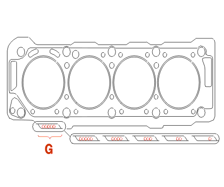
(G) : Thickness identification .
There are 5 categories of laminated metal cylinder gaskets .
The cylinder head gasket fits both DW10 ATED and DW10 TD engines .
Method for selecting the gasket by measuring the piston protrusion (Identical to DW8 engine) .
| piston protrusion measurements (mm) | thickness (mm) | notch(es) number of holes at (G) |
|---|---|---|
| 0.47 to 0.604 | 1.30 ± 0.06 | 1 |
| 0.605 to 0.654 | 1.35 ± 0.06 | 2 |
| 0.655 to 0.704 | 1.40 ± 0.06 | 3 |
| 0.705 to 0.754 | 1.45 ± 0.06 | 4 |
| 0.755 to 0.83 | 1.50 ± 0.06 | 5 |
6 - 7 - TAPPETS (OPERATION)
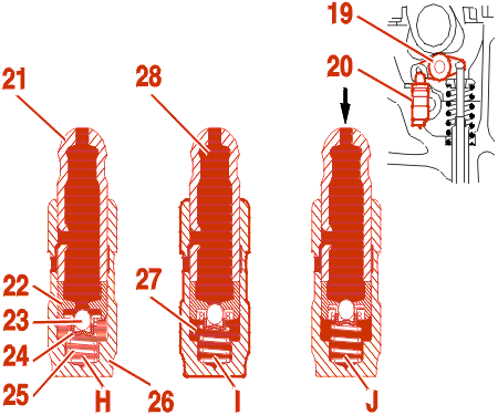
(19) Roller cam follower .
(20) Hydraulic tappet .
(21) Ball joint .
(22) Piston .
(23) Valve .
(24) Return spring .
(25) Return spring .
(26) Barrel .
(27) Lower chamber .
(28) Upper chamber .
The 12 mm diameter hydraulic tappets have automatic clearance take-up .
Cam - valve clearance take-up phase (H - I) :
Compression phase (valve lift) (J) :
6 - 8 - VALVES
Special valves :
Valve stem (Diameter 5.978 mm) .
6 - 9 - VALVE SPRINGS
External diameter : 20.9 mm .
Number of coils : 9 .
7 - TIMING
7 - 1 - DATA
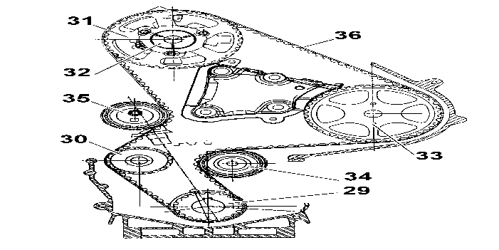
(29) crankshaft gear (21) teeth .
(30) Coolant pump gear (20 teeth) .
(31) Camshaft gear (42 teeth) .
(32) Camshaft hub .
(33) High pressure pump pinion (42 teeth) .
(34) Roller tensioner (External diameter : 60 mm) .
(35) Manual tensioner roller (60 mm diameter and eccentric radius 7 mm) .
(36) Timing belt .
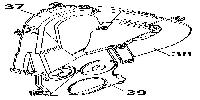
Timing cover in 3 sections secured by 9 bolt(s) :
7 - 2 - TIMING BELT
| engine code | RHZ | RHY |
|---|---|---|
| engine type | DW10 ATED | DW10 TD |
| width (mm) | 25.4 | |
| number of teeth | 141 | |
| supplier(s) | DAYCO | |
| material | HSN | |
| identification mark | - | |
| replacement interval (km) in normal conditions of use |
160 000 | |
| replacement interval (km) in arduous conditions of use |
120 000 | |
NOTE : the belt is tensioned on fitting by the manual tensioner roller (eccentric) requiring the fitting of the SEEM tension checking equipment .
7 - 3 - HIGH PRESSURE PUMP
The high pressure pump has three radial pistons and is driven in a non synchronous manner by the timing .
8 - LUBRICATION
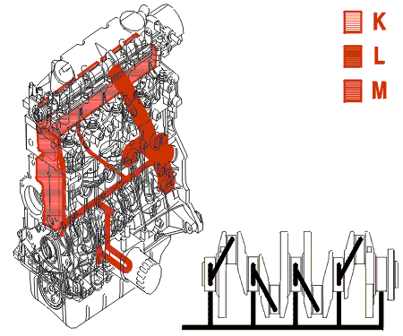
(K) : Low pressure oil descent circuit .
(L) : Oil vapour descent circuit from the top of the engine .
(M) : High pressure oil ascent circuit .
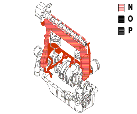
(N) : Low pressure oil descent circuit .
(O) : Oil vapour descent circuit from the top of the engine .
(P) : High pressure oil ascent circuit .
8 - 1 - OIL CAPACITY
depending on the use of the vehicle, the engine can be tilted or straightened: adaptation to each vehicle .
| straight engine | ||
|---|---|---|
| engine code | RHY - RHZ | RHY - RHZ |
| special features | air conditioning | without air conditioning |
| oil capacity (with filter) | 4.5 | 4.5 |
| oil capacity (without filter) | 4.2 | 4.2 |
| tilted engine | ||
|---|---|---|
| engine code | RHY - RHZ | RHY - RHZ |
| special features | air conditioning | without air conditioning |
| oil capacity (with filter) | 4.25 | 4.25 |
| oil capacity (without filter) | 4 | 4 |
IMPERATIVE : always check the oil level using the dipstick .
Oil change interval (Engine oil) : Refer to the maintenance documents .
8 - 2 - ENGINE OIL FILTER CARTRIDGE
Oil filter cartridge (First assembly) :
Oil filter cartridge (Spare) :
Replacement interval (Engine oil filter cartridge) : Refer to the maintenance documents .
8 - 3 - LUBRICATION SYSTEM
The piston bases are cooled by jets .
Engine oil pressure at 80°C measured in place of the pressure switch .
| engine code | RHZ | RHY |
|---|---|---|
| check 1 minimum pressure (bar(s)) |
1000 rpm 2 |
1000 rpm 2 |
| check 2 minimum pressure (bar(s)) |
2000 rpm 2.8 |
2000 rpm 2.8 |
| check 3 minimum pressure (bar(s)) |
3000 rpm 3.8 |
3000 rpm 3.8 |
| check 4 minimum pressure (bar(s)) |
4000 rpm 4 |
4000 rpm 4 |
8 - 4 - ENGINE OIL CHANGE
The engine oil must be changed with the engine hot just after switching off the engine .
The engine can be drained by suction (End piece ø 14 mm) .
It is still possible to drain the engine by removing the drain plug from the sump .
9 - AIR SUPPLY CIRCUIT
9 - 1 - THE INDUCTION CIRCUIT
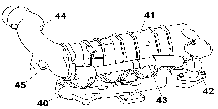
(40) Exhaust manifold (Cast iron) .
(41) Inlet manifold (Aluminium alloy) .
(42) EGR valve .
(43) EGR valve/manifold connection pipe .
(44) The air inlet hose (Aluminium alloy) .
(45) Vacuum pump .
The Exhaust Gas Recirculation pipe is secured by :
The EGR valve (42) is secured by 2 bolts on the exhaust manifold (40) .
9 - 2 - EXHAUST GAS RECIRCULATION
The role of the EGR system is to reduce the amount of nitrous oxide (NOx) expelled in the exhaust gases .
The nitrous oxides are produced by the combination of the nitrogen and the oxygen in the intake air under the effect of a very high temperature (greater than 1800 degrees C) .
During certain phases of operation the EGR reduces the amount of oxygen available in the cylinder .
The EGR valve (42) is subjected to a vacuum from the vacuum pump (45) secured at the end of the camshaft and this authorises recirculation of the exhaust gases to the air union (44) .
The recirculation is of the progressive type managed by mapping .
The opening of the EGR valve (42) is controlled by the EGR solenoid valve which is managed by the engine management control unit which receives the following data :
9 - 3 - TURBOCHARGER PRESSURE REGULATION SOLENOID VALVE
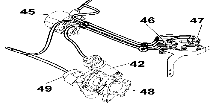
(42) EGR valve .
(45) Vacuum pump .
(46) Turbocharger pressure regulation solenoid valve .
(47) EGR solenoid valve .
(48) Turbocharger .
(49) Turbo regulation valve .
Controlled by the ECU, this solenoid valve enables it to regulate the intake pressure via the turbo regulation valve (49) .
10 - PRE-POST HEATING
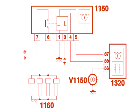
(1150) Pre-heat control unit .
(1160) Glow plugs .
(1320) Engine management control unit .
(V1150) Pre-heat warning lamp .
10 - 1 - PRE-HEATING
As soon as ignition is switched on : The engine management control unit supplies the glow plugs and controls the lighting of the warning light on the instrument panel, depending on the coolant temperature; The pre-heating time varies depending on the coolant temperature .
NOTE : the warning light on the instrument panel only comes on during the pre-heating phase; it comes on for the duration of the pre-heating .
| coolant temperature | pre-heating time (second(s)) |
|---|---|
| -30°C | 20 |
| -10°C | 5 |
| 0°C | 0.5 |
| +18°C | 0 |
If the starter is not operated, when the warning light goes out, the glow plugs remain supplied for a maximum of 10 seconds .
During the starting phase, the glow plugs are supplied under the following conditions :
10 - 2 - POST HEATING
Post-heating consists of prolonging the operation of the glow plugs for a maximum of 60 seconds from the end of the starting phase .
Parameters which could interrupt post-heating :
11 - FUEL SYSTEM
11 - 1 - PRESENTATION
This engine is fitted with a new COMMON RAIL direct injection system from BOSCH .
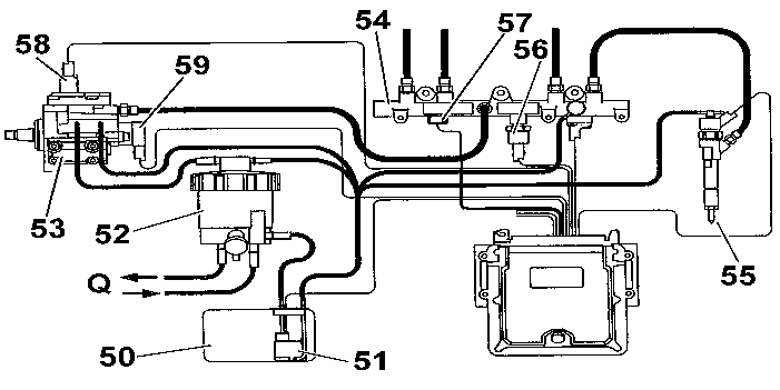
(50) Fuel tank .
(51) Scavenge pump .
(52) Fuel filter .
(53) High pressure pump .
(54) Common rail .
(55) Injector .
(56) Diesel pressure sensor .
(57) Diesel temperature sensor .
(58) Third piston de-activator .
(59) Diesel high pressure regulator .
(Q) To coolant outlet housing .
11 - 2 - FILTRATION RESERVOIR ASSEMBLY
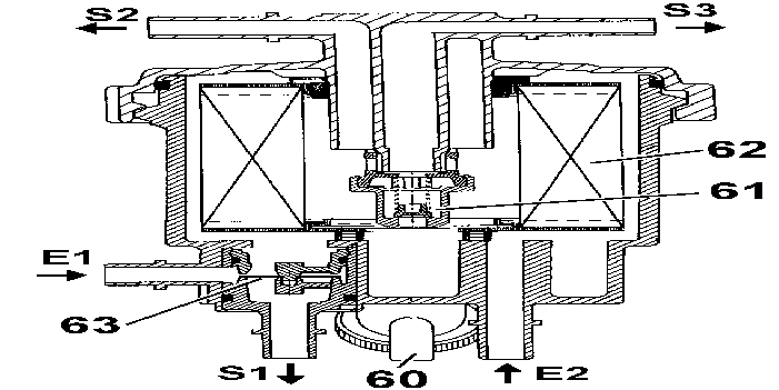
(E1) Diesel inlet from tank .
(E2) Diesel inlet from coolant outlet housing .
(S1) Diesel outlet : To coolant outlet housing .
(S2) Diesel outlet : To high pressure pump .
(S3) Diesel outlet to tank (return circuit) .
(60) Bleed screw (Water in diesel fuel) .
(61) Low pressure regulator .
(62) Filtering element .
(63) Thermostatic element .
Filtration of impurities bigger than 5 microns .
Replacement interval (Diesel filter cartridge) : Refer to the maintenance documents .
11 - 3 - DIESEL HEATER
The fuel is heated by the cooling circuit (on the coolant outlet housing) .
The temperature of the fuel is regulated by a thermostatic element (63) (incorporated in the filtration reservoir) .
11 - 4 - OPERATING PHASE (THERMOSTATIC ELEMENT)
The thermostatic element (63) is a bimetallic strip which deforms according to the temperature of the fuel .
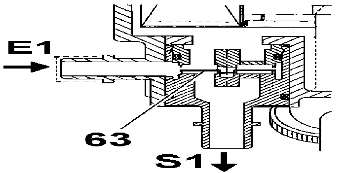
Fuel temperature below 15 degrees C :
Temperature between 15 and 25 degrees C :
Temperature above 25 degrees C :
11 - 5 - LOW PRESSURE REGULATOR
The scavenge pump (51) generates a supply pressure of 2.25 ± 0.25 bars .
The low pressure regulator (61) regulates the pressure after filtration of the diesel to 1.25 ± 0.25 bars .
12 - COOLING SYSTEM
12 - 1 - SCHEMATIC DIAGRAM
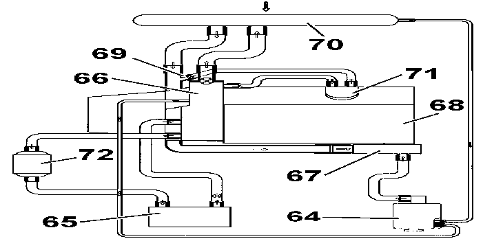
(64) Expansion chamber .
(65) heater matrix .
(66) Water outlet housing .
(67) Water inlet housing .
(68) Coolant pump (To cylinder block) .
(69) Bleed screw .
(70) The cooling radiator .
(71) Water/fluid heat exchanger (12 blades) .
(72) Water circuit heater (Additional heating) .
13 - DRIVING THE ANCILLARIES
There are 2 possibilities (depending on the vehicle and the level of specification) :
13 - 1 - POWER STEERING + ALTERNATOR
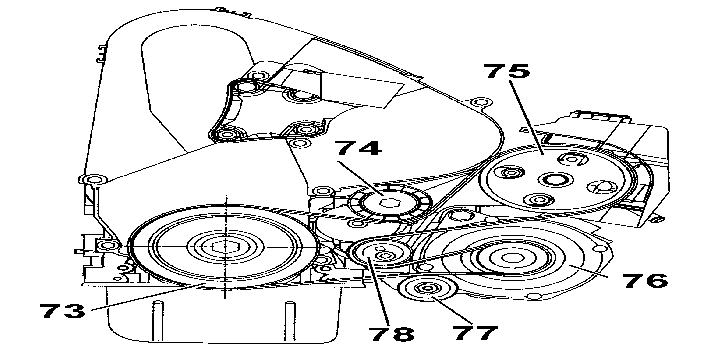
(73) Crankshaft pulley .
(74) Dynamic tensioner roller .
(75) Power steering pump .
(76) Alternator .
(77) Stabiliser roller .
(78) Roller tensioner (The belt fitting tension is adjusted by means of a cam ring) .
13 - 2 - AIR CONDITIONING + POWER STEERING + ALTERNATOR
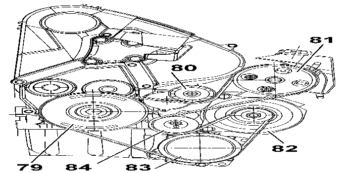
(79) Crankshaft pulley .
(80) Dynamic tensioner roller .
(81) Power steering pump .
(82) Alternator .
(83) Air conditioning compressor .
(84) Roller tensioner (The belt fitting tension is adjusted by means of a cam ring) .