B1CJ0DK1 - 406D9 XU5JP ENGINE XU7JP ENGINE XU7JB ENGINE
REASSEMBLY 8 VALVE ENGINE(S) (TIMING)
1 - SPECIAL TOOLS
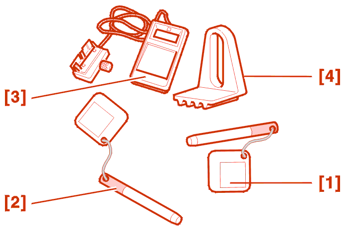
| reference | description | reference | reference |
|---|---|---|---|
| [1] | camshaft pinion setting rod ( XU10/806 engine) |
(-).0132-R (-).0153-AA |
7018 - T.Y |
| [2] | crankshaft setting rod | (-).0153-G (-).0132-R |
7014 - T.N |
| [3] | tension measuring equipment | SEEM | SEEM |
| [4] | flywheel stop | FACOM D.86 | 6012 - T/9044 - T |
2 - REASSEMBLY
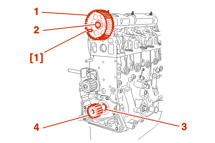
Fit the camshaft gear (1) .
Peg the camshaft using tool .
Tighten the bolt (2) :
On the crankshaft, refit :
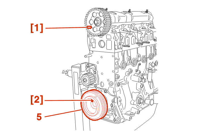
Offer up the pulley (5) to the crankshaft .
Check with the rod [2] that the crankshaft is correctly timed .
Remove :
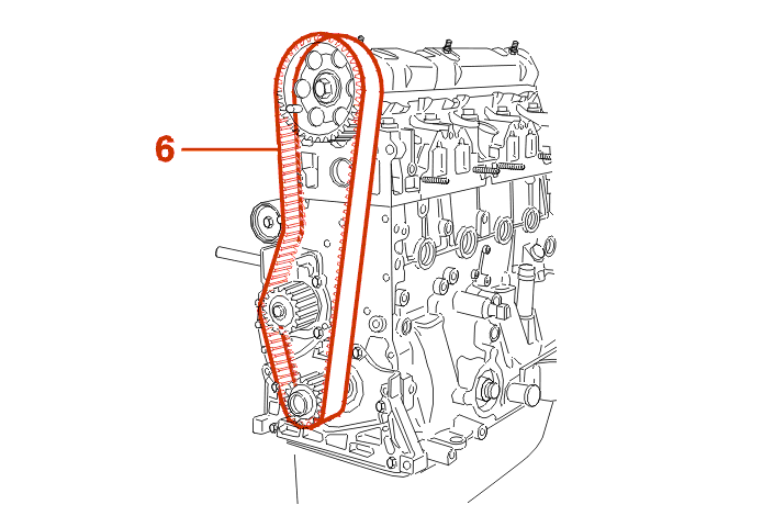
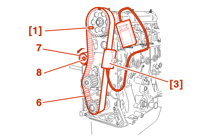
Observing its direction of fitting and the markings, fit the belt, run (6) well tensioned, in the following order :
Fit :
WARNING : turn the roller tensioner anti-clockwise to tension the belt (6) lightly .
Nip up the bolt (8) .
On the run (6), position the belt tensioning equipment [3] .
Turn the roller tensioner anti-clockwise to display 30 ± 2 SEEM units .
Tighten the bolt (8) to 2.1 da.Nm + LOCTITE FRENETANCH .
Remove :
3 - CHECKING BELT TENSION
Turn the engine over 2 times in the normal direction of rotation .
Check that the valve timing is correct by fitting the rods [1] and [2] .
Remove the setting pins .
Turn the crankshaft another 2 turns in the direction of running .
IMPERATIVE : never turn the crankshaft in the reverse direction .
Fit the rod [1] .
Position the equipment [3] .
The tension value should be between 42 and 46 SEEM units .
If this is not the case, restart the timing belt tensioning operation .
XU5JP ENGINE
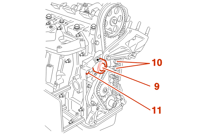
Fit :
Run up the bolts (10) .
Place the cam (11) horizontally, with the spring compressed .
WARNING : check that the roller tensioner (9) turns freely (no tight spot) .
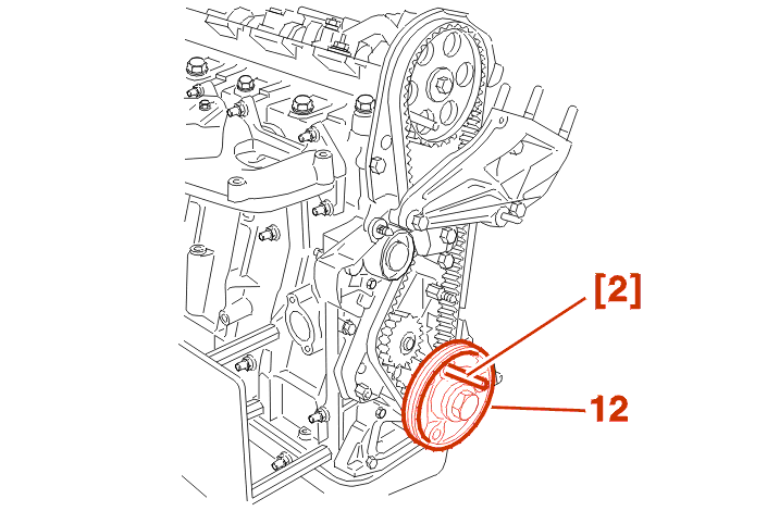
Offer up the pulley (12) to the crankshaft .
Check with the rod [2] that the crankshaft is correctly timed .
Remove :
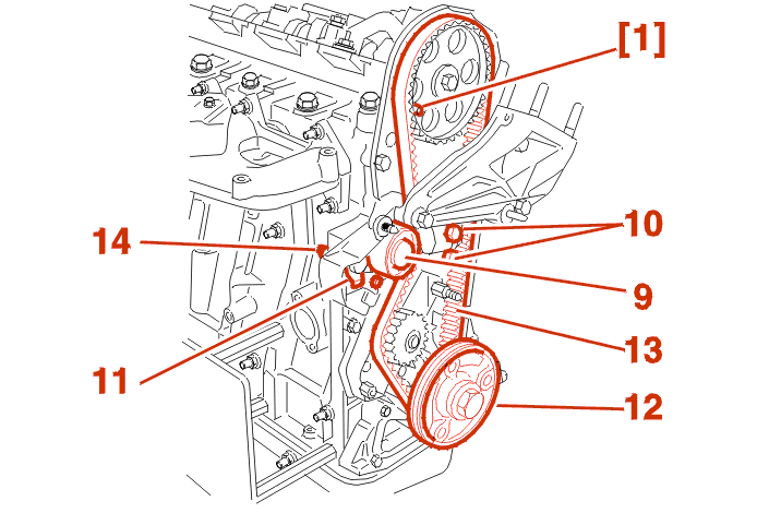
Observing its direction of fitting and the markings, fit the belt, run (13) well tensioned, in the following order :
Remove the rod [1] .
Position the cam (11) downwards .
Tighten the bolts (10) .
Turn the crankshaft 2 turn(s) in the direction of running .
Slacken the bolts (10) to free the tensioner roller (9) .
Tighten the bolts (10) to 1.5 da.Nm. .
Tighten the nut (14) to 1.5 da.Nm .
Turn the engine over 2 times in the normal direction of rotation .
Check that the valve timing is correct by fitting the rods [1] and [2] .
Remove :
Repeat the operation (if necessary) .
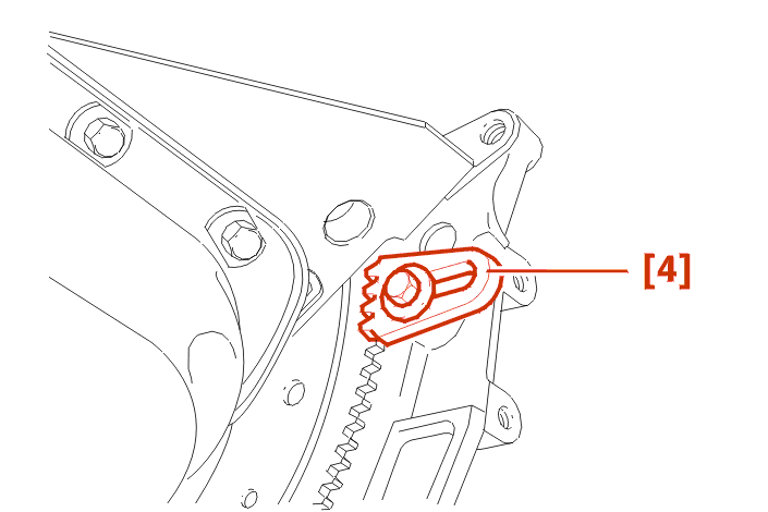
ALL MODELS
Lock the flywheel with the stop [4] .
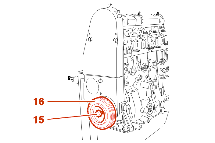
WARNING : never tighten the bolt (15) with the rod [2] in place (risk of damage) ; use the flywheel retainer [4] .
Remove :
Coat the bolt (15) with threadlock LOCTITE .
Tighten the bolt (15) to 13 da.Nm .
Route and clip exactly as before .