B1EG1MK1 - 406D9 ES9J4 ENGINE
REMOVAL - REFITTING TIMING BELT
1 - SPECIAL TOOLS
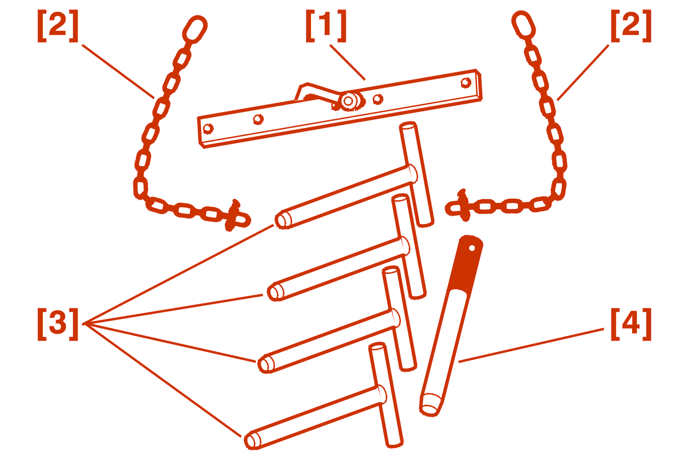
[1] cross beam (-).0102-D .
[2] Lifting chain (-).0102-M .
[3] Camshaft setting rods (-).0187-B .
[4] crankshaft setting rod (-).0187-A .
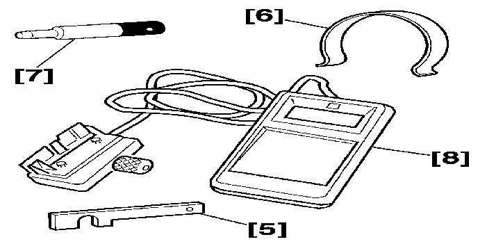
[5] Timing dynamic tensioner setting gauge (-).0187-EZ .
[6] Belt retaining clip (-).0187-J .
[7] Camshafts setting check rod (-).0187-CZ .
[8] SEEM C.TRONIC 105.5 tension measuring equipment .
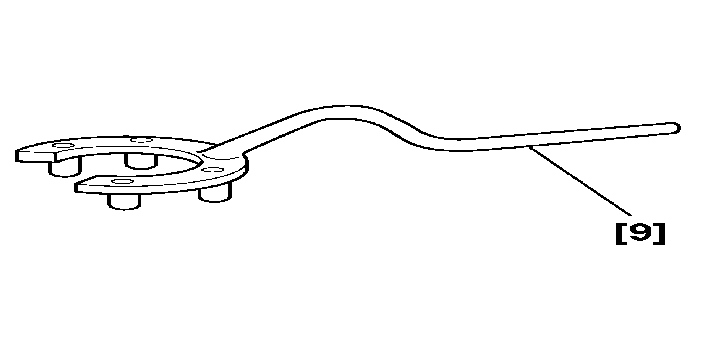
[9] Camshaft hub immobilisation tool (-).0187-F .
2 - REMOVAL
Remove the shield under the power train .
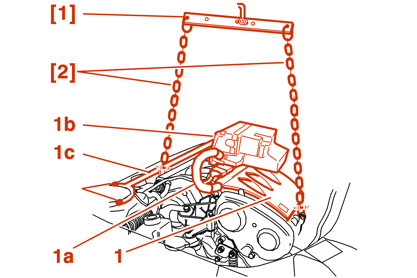
Remove the style cover (1) .
Disconnect the connector (1a) .
Move aside :
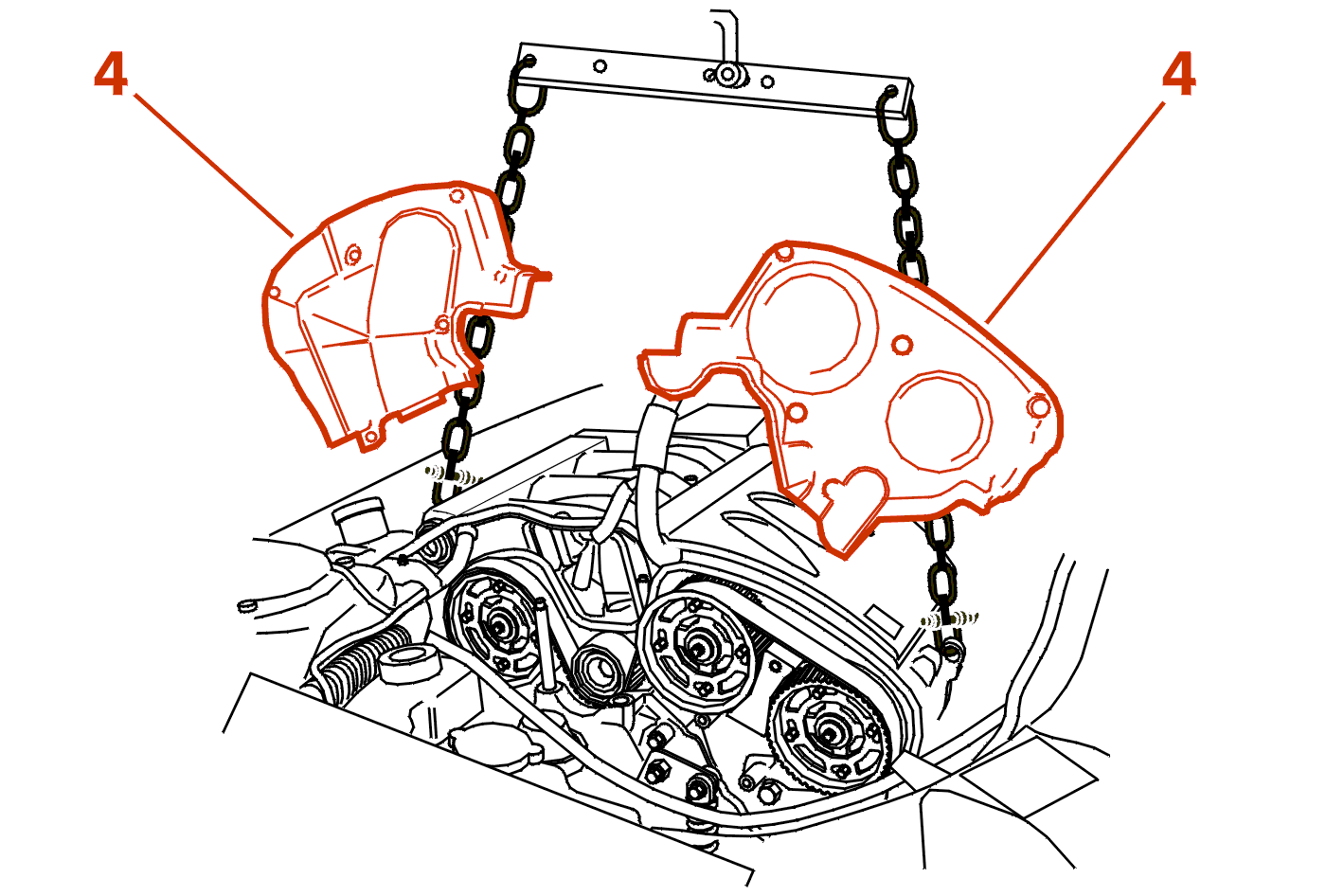
Position the cross beam [1] fitted with its chains [2] and take the weight .
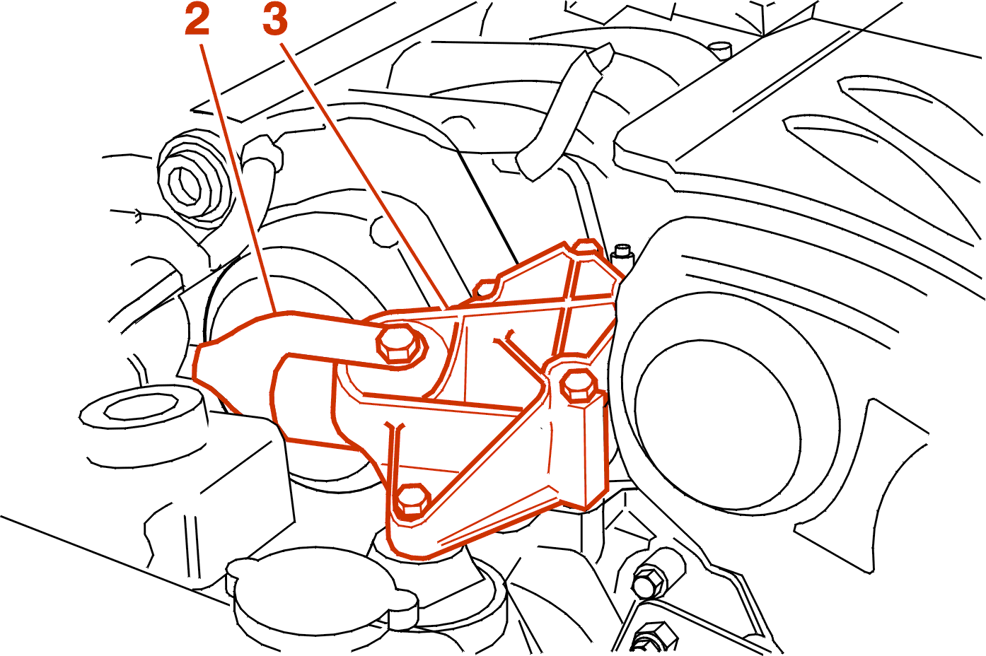
Remove :
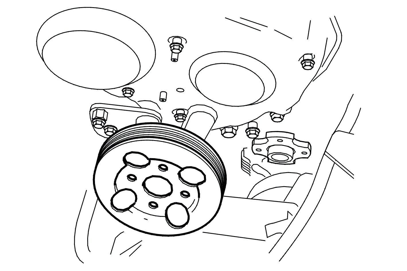
Remove :
Remove :
Remove :
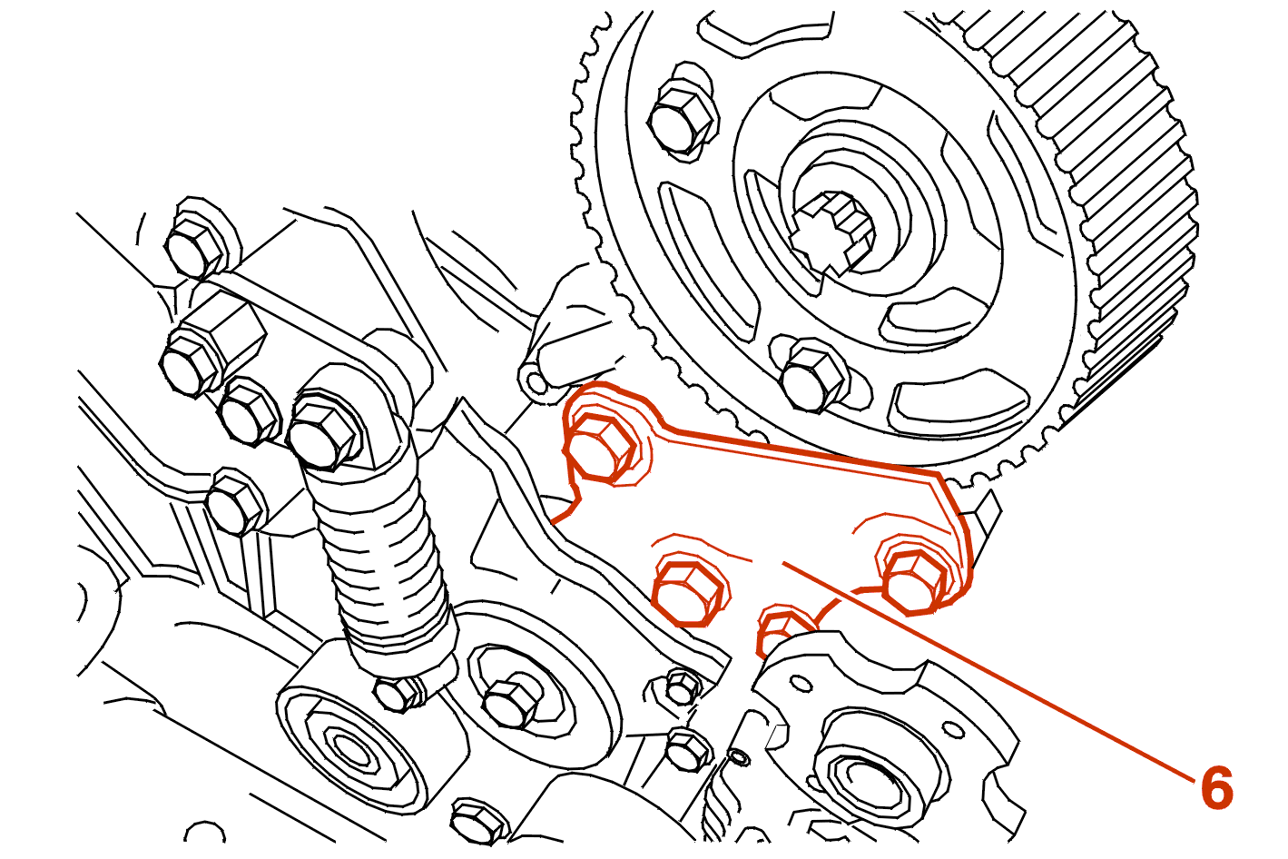
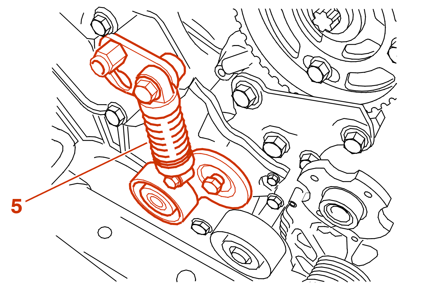
Remove :
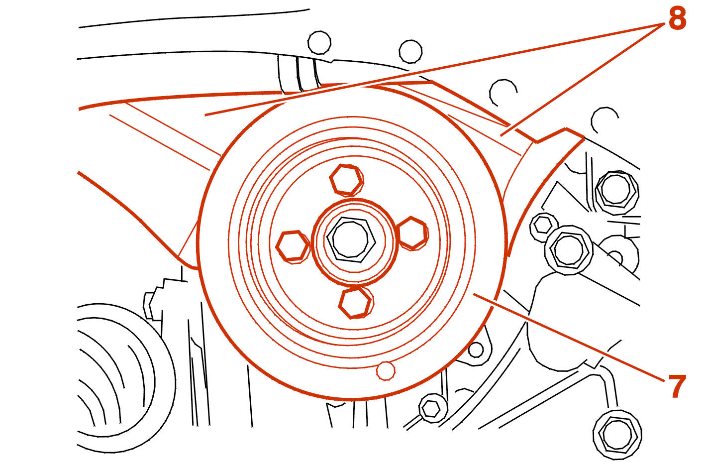
Remove :
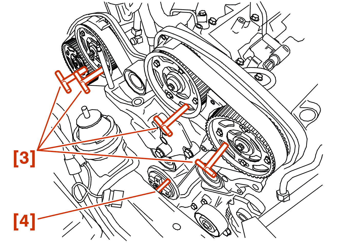
NOTE : the operation to peg the camshafts is made easier by first slackening the pinion bolts and turning the camshafts (using the tool [9]), lightly oil the rods [3] before assembly .
Peg in the order :
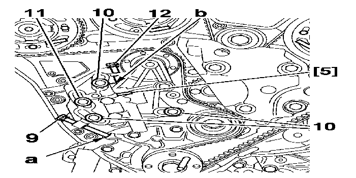
Position 1 bolt(s) (9) type M8 x 125 x 75 .
Start to tighten the bolt (9) until it touches at (a) .
IMPERATIVE : the spacer bolt (11) must remain fully tightened .
Slacken the bolts (10) .
Position :
Start to tighten the bolt (12) until it touches at (b) .
Tighten the bolt (12) until the tool [5] is fully tightened .
Unscrew the bolt (9) to the maximum .
IMPERATIVE : if the belt is to be re-used mark the direction of rotation .
Remove the timing belt .
3 - REFITTING
Ensure that the camshafts and the crankshaft timing are correct .
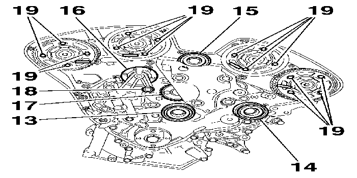
Check that the rollers (13), (14), (15), (16) as well as the coolant pump (17) turn freely (no play or hard spots) .
In the event of replacement, Tightening torques :
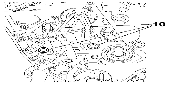
Tighten the bolts (10) to 1 ± 0.1 daN.m .
Slacken the bolts (10) by 45° .
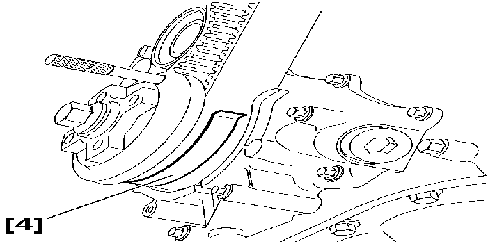
IMPERATIVE : when re-using the belt, refit it in the direction of rotation marked during removal .
Engage the timing belt on the crankshaft pinion .
Immobilise the belt using the tool [4] .
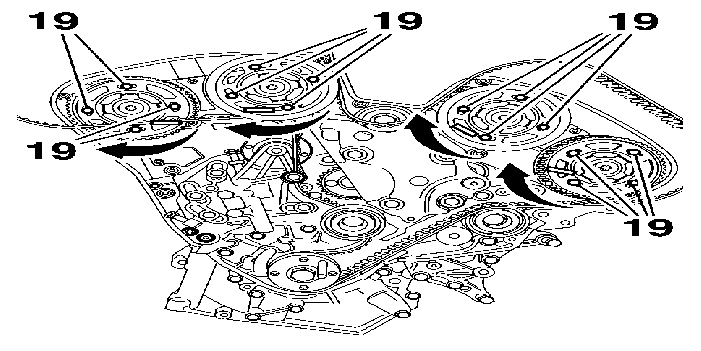
Check that the camshaft pinions rotate freely on their hubs .
Turn the 4 camshaft pinions clockwise as far as the stop at the end of the slots .
Tighten the bolts (19) to 0.5 ± 0.03 daN.m .
Slacken the bolts (19) by 45° .
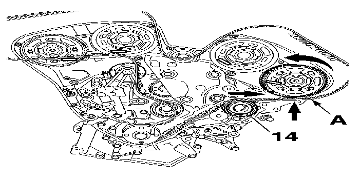
Position the belt on the free-rolling roller (14) .
Span (A) of the belt correctly tensioned .
Slightly turn the camshaft pinion in the opposite direction to the rotation of the engine in order to engage the belt on the pinion .
Locate the belt on the camshaft pinion, left-hand exhaust .
IMPERATIVE : the angular displacement value of the pinion in relation to the timing belt must not be greater than the width of one tooth .
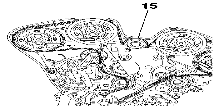
Engage the belt :
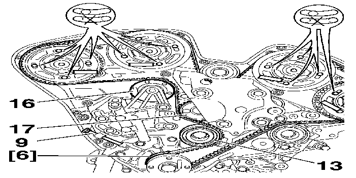
Engage the belt simultaneously :
Run up the bolt (9) to make the belt seat correctly .
IMPERATIVE : check that the camshaft pinions are not at the end of the slots (by removing a bolt) .
If this is not the case, restart the belt fitting operation .
Remove the tool [6] .
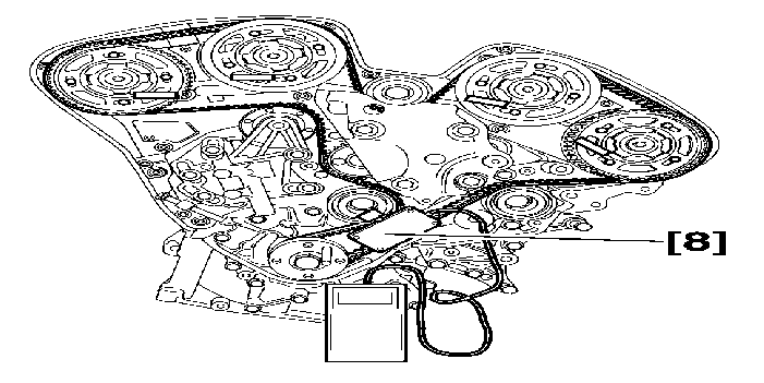
Place the tool [8] on the timing belt .
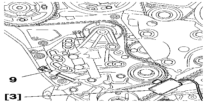
Operate the dynamic tensioner using the bolt (9) until 83 ± 2 SEEM units are obtained .
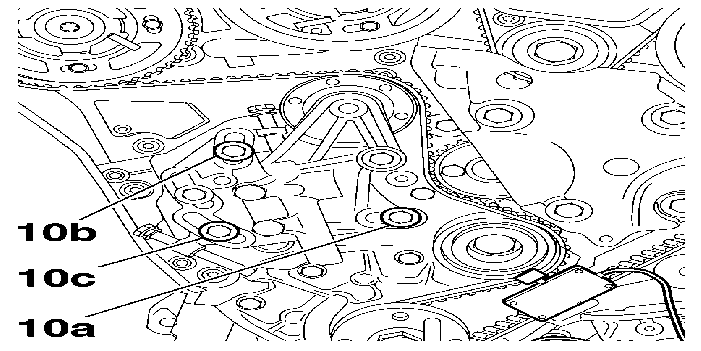
Tighten in the order :
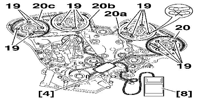
Tighten in the order :
Remove :
Turn the engine over 2 times in the normal direction of rotation .
IMPERATIVE : never turn the crankshaft in the reverse direction .
Fit :
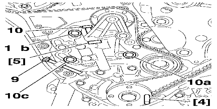
Slacken by 45 degrees :
Remove the bolt (12) .
Adjust the bolt (9), in order to ensure that the tool [5] slides without play .
Wait at least 1 minute (damper action) if the ambient temperature is higher than 15 °C, otherwise, wait a little longer .
Check that the tool [5] slides .
Remove the tool [5] .
Tighten in the order :
Remove :
Turn the engine over 2 times in the normal direction of rotation .
IMPERATIVE : never turn the crankshaft in the reverse direction .
Fit :
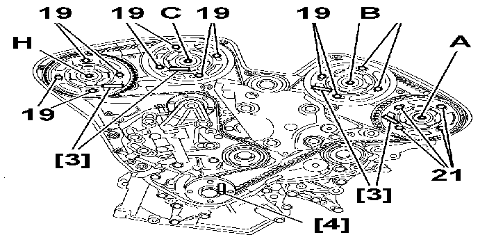
Peg the camshaft (A) using a rod [3] .
NOTE : if the rod [3] does not fit into its housing : fit the tool [9] ; slacken the bolts (19) by 45° ; peg the camshaft by means of the rod [3], using the tool [9] .
NOTE : if the rod [3] fits into its housing : slacken the bolts (19) by 45° .
Peg the camshaft (B) using a rod [3] .
NOTE : if the rod [3] does not fit into its housing : fit the tool [9] ; slacken the bolts (19) by 45° ; peg the camshaft by means of the rod [3], using the tool [9] .
NOTE : if the rod [3] fits into its housing ; slacken the bolts (19) by 45° .
Carry out the same procedure for camshafts (C) and (D) .
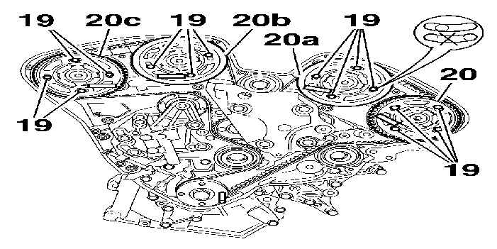
IMPERATIVE : check that the camshaft pinions are not at the end of the slots (by removing a bolt) .
If this is not the case, restart the belt fitting operation .
Tighten in the order :
Remove :
4 - CHECKING THE VALVE TIMING
Turn the engine over 2 times in the normal direction of rotation .
IMPERATIVE : never turn the crankshaft in the reverse direction .
Fit :
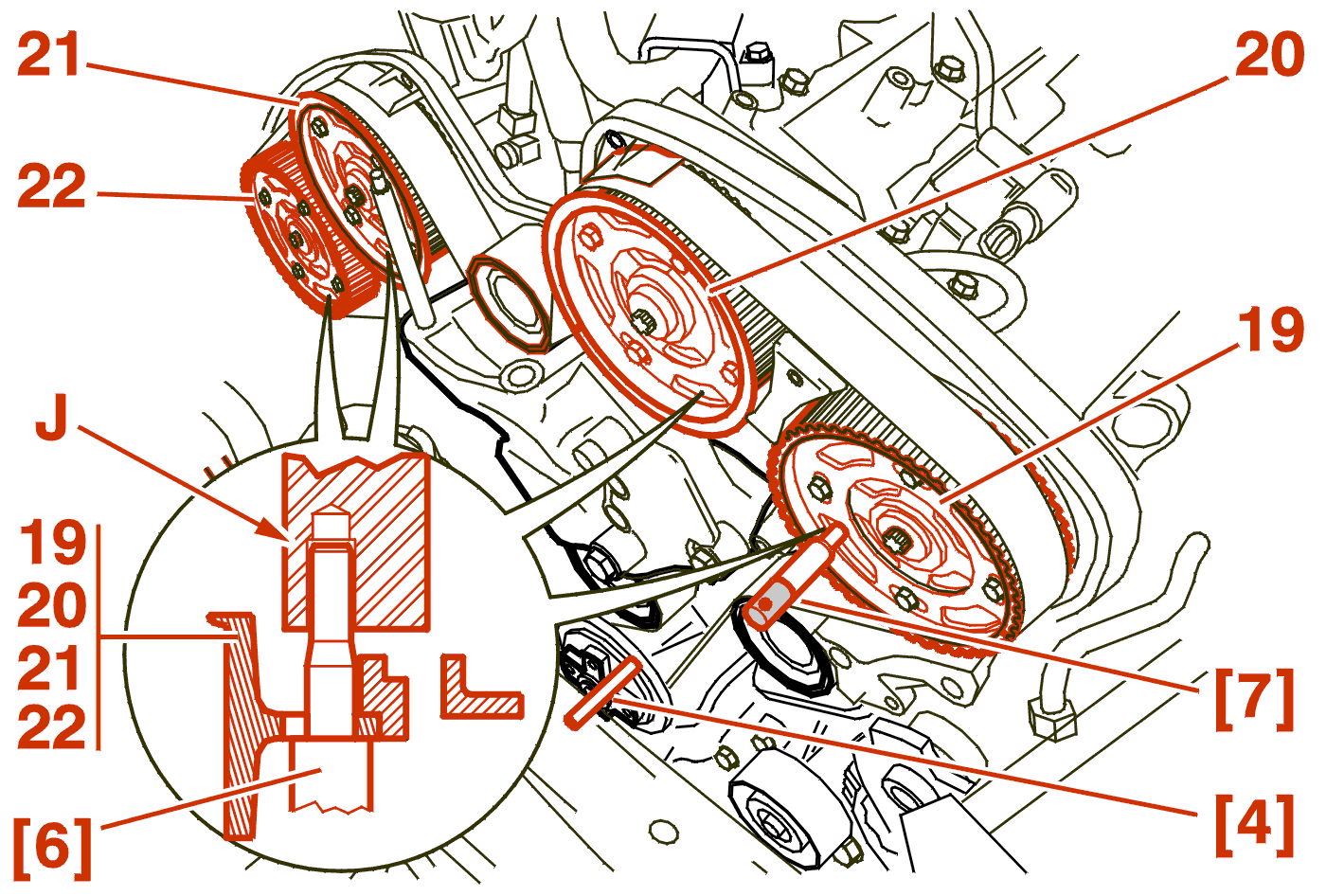
Check that the camshafts checking rod [6] engages freely in the cylinder heads (J) stopping at the camshaft pinions .
If this is not the case, restart the belt fitting operation .
Remove :
5 - REFITTING (CONTINUED)
Proceed in the reverse order to removal .
Tighten :
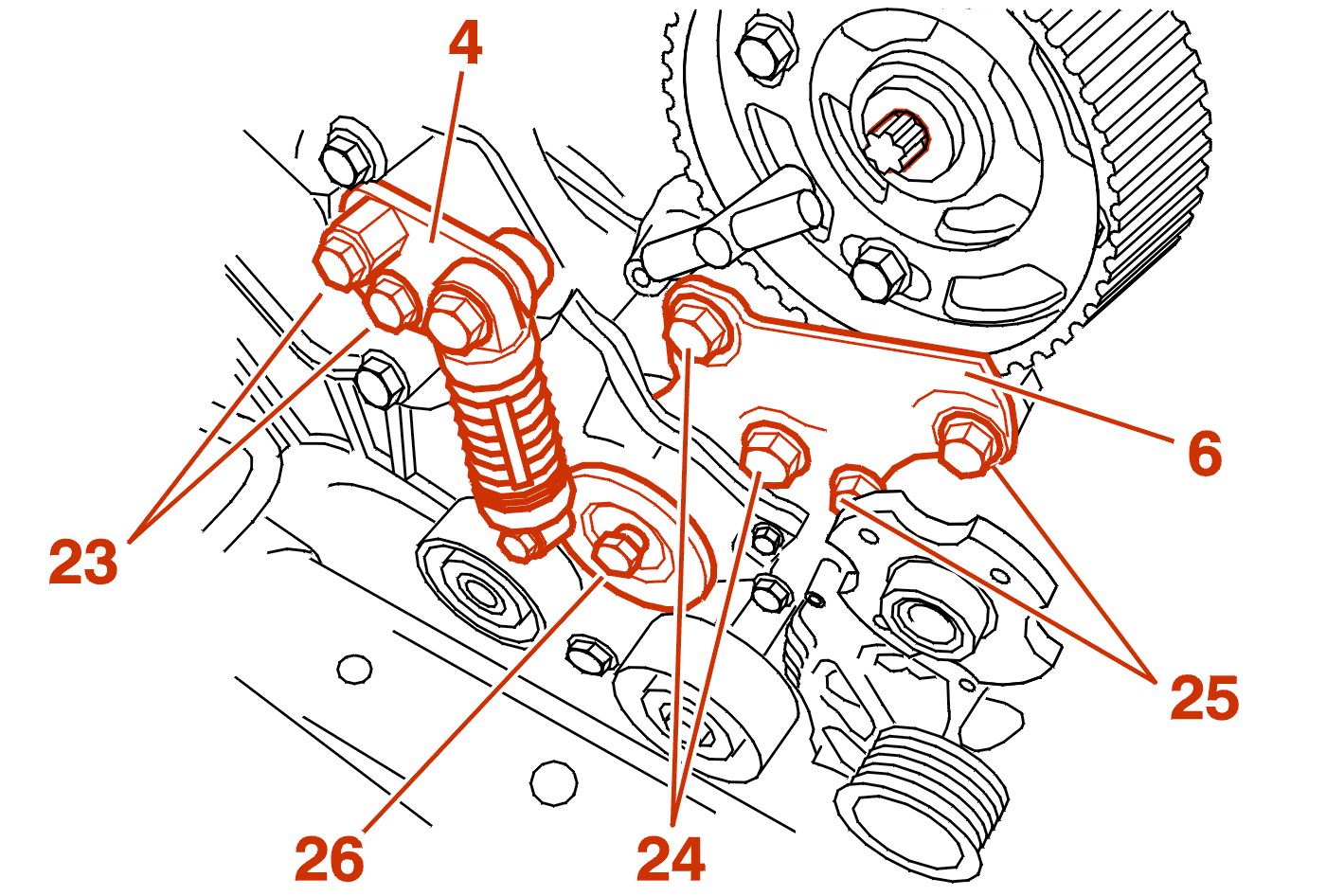
Fit :
Refit the bolts (23) .
Tighten :
Fit :
Tighten :
fit the ancillary drive belt .
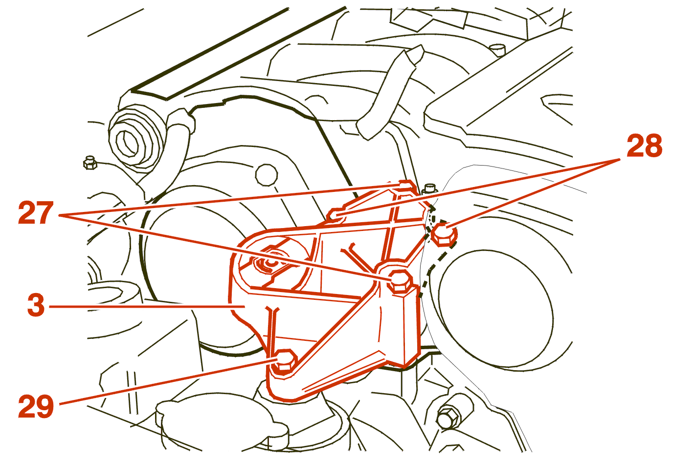
Refit the right-hand engine mounting (3) .
Tighten :
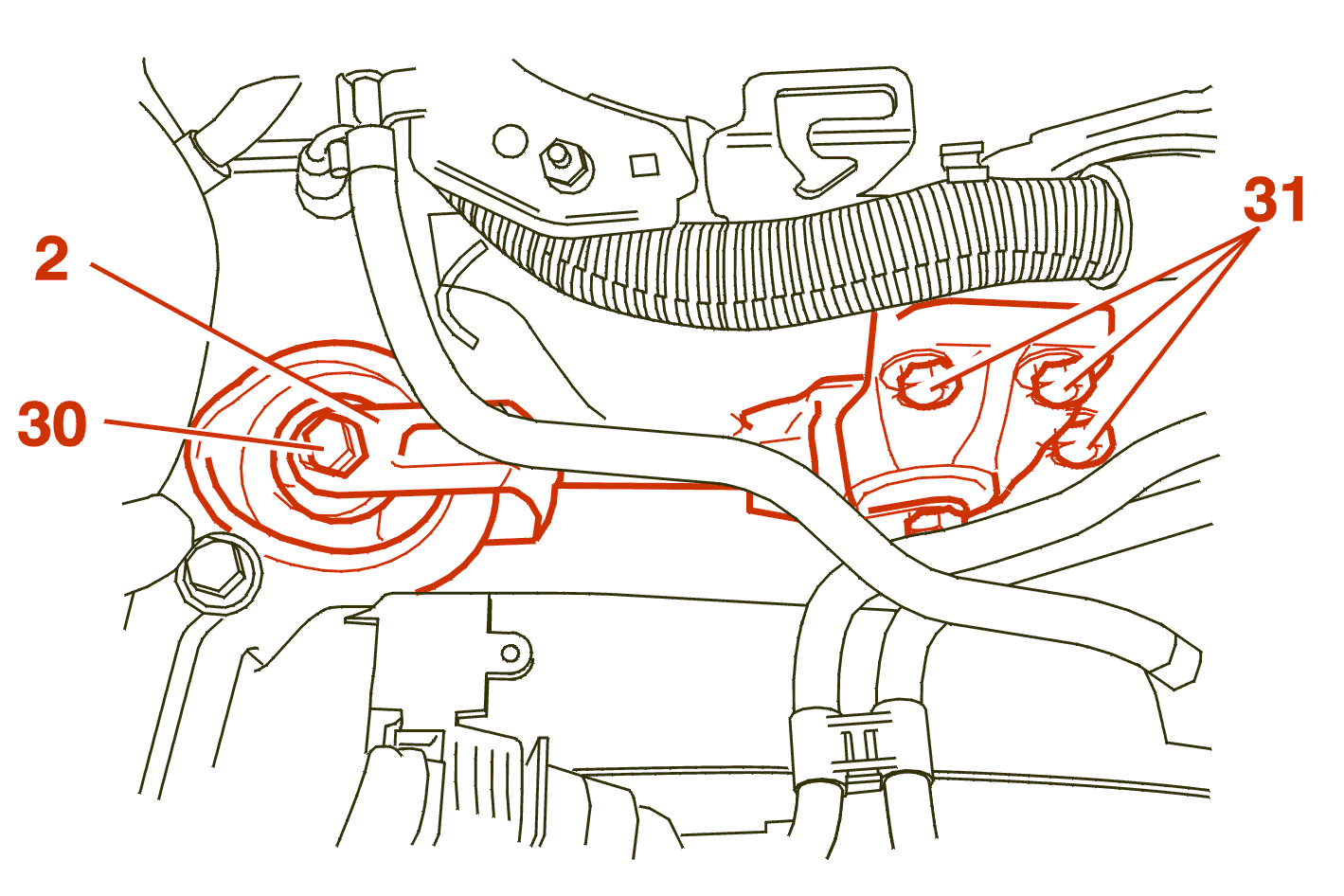
Refit the torque reaction link (2) .
Tighten :
Continue the fitting operations in the reverse order to removal .