B2FH00K1 - 406D9
REPLACEMENT DRIVE SHAFT GAITERS TYPE GLAENZER SPICER (GKN)
NOTE : this operation can be carried out following two different methods, depending on the tools available .
1 - SPECIAL TOOLS
1 - 1 - 1ST METHOD
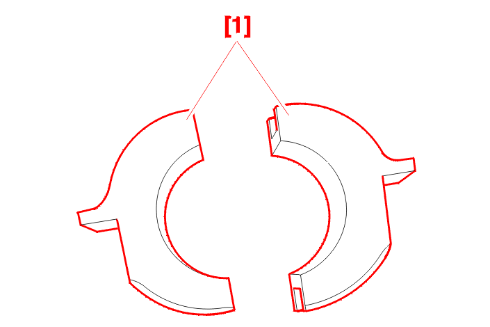
| reference | description | reference | reference |
|---|---|---|---|
| [1] | drive shaft bracket | (-).0403-R | (-).0403-R |
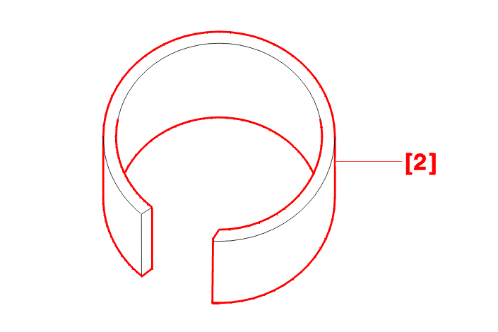
| reference | description | reference | reference |
|---|---|---|---|
| [2] | drive shaft retaining ring ø 72 mm | (-).0410-D | 4101-T |
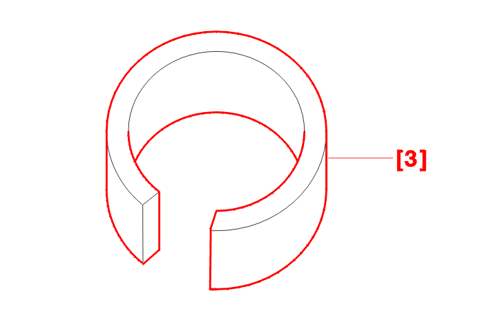
| reference | description | reference | reference |
|---|---|---|---|
| [3] | drive shaft retaining ring ø 65 mm | (-).0410-F | 4518-T |
1 - 2 - 2ND METHOD
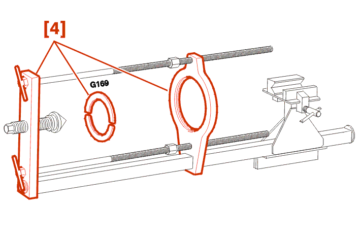
| reference | description | reference | reference |
|---|---|---|---|
| [4] | gaiter fitting tool on final drive end with metal supports for all models | (-).0410-M | (-).0410-M |
1 - 3 - 1ST AND 2ND METHODS
| reference | description | reference | reference |
|---|---|---|---|
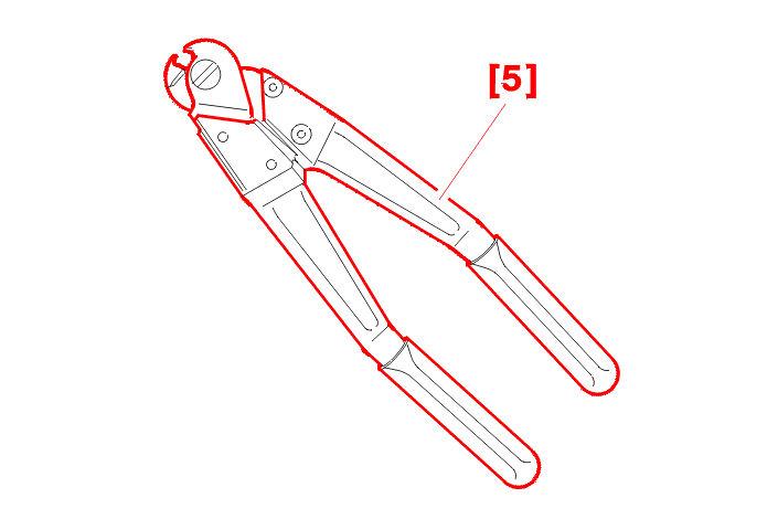
| [5] | CLIC clip pliers | (-).0409 | 4178-T |
| reference | description | reference | reference |
|---|---|---|---|
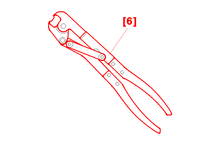
| [6] | clip pliers : OETIKER | (-).0408 | 4151-T |
2 - REPLACEMENT OF THE GAITER AT THE GEARBOX END
2 - 1 - 1ST AND 2ND METHODS
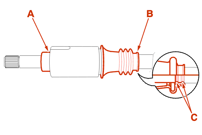
Place a piece of adhesive tape on the surface (A) .
For driveshafts which do not have a positioning groove (C), Mark the position of the gaiter (B) .
2 - 2 - 1ST METHOD
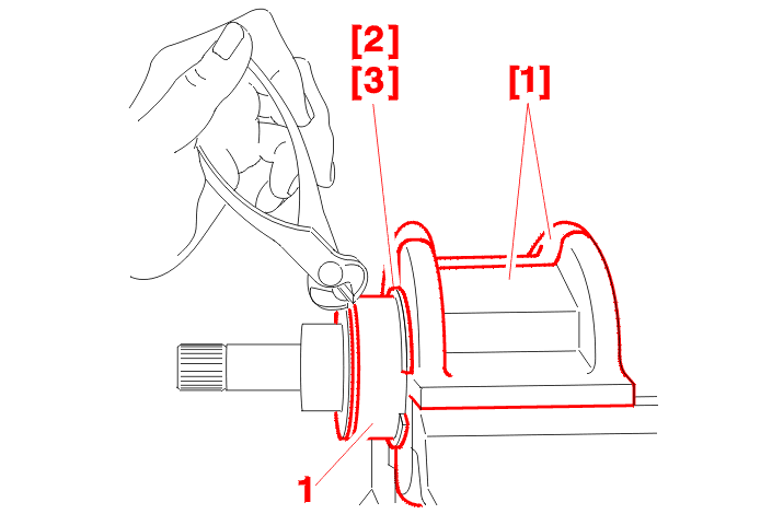
Place the drive shaft in a vice using tools [1] and [2] or [3], depending on the diameter of the spider housing .
Uncrimp the spider housing (1) using pliers .
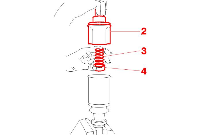
Remove :
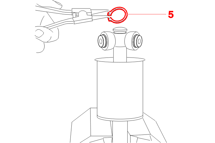
Remove the circlip (5) .
Mark the position of the spider in relation to the shaft .
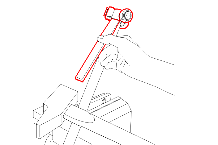
Remove :
Remove as much of the old grease as possible .
IMPERATIVE : do not use solvents .
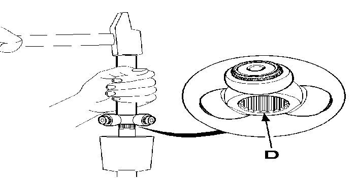
Fit :
Fill the gaiter with all the grease available in the repair kit .
Fit :
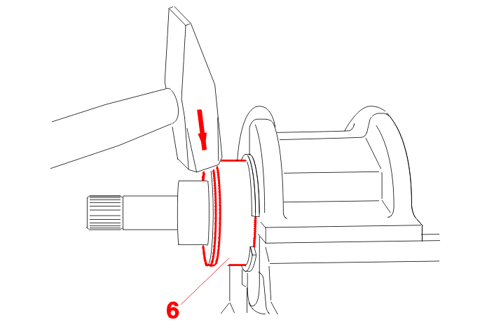
Crimp the spider housing (6) .
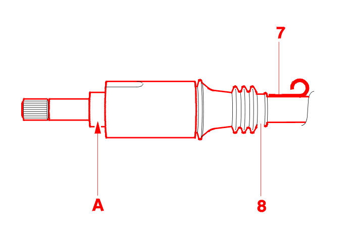
Gaiter with breather ring :
Gaiter without breather ring :
2 - 3 - 2ND METHOD
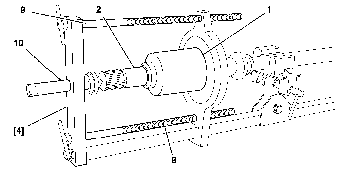
Fit the driveshaft on the tool [4] .
Uncrimp the spider housing (1) using pliers .
For the subsequent operations, proceed as in the first method .
On refitting, position the gaiter using the bolts (9) .
Compress the inner joint (2) moderately using the bolt (10) .
Crimp the spider housing using a hammer and a chisel .
For the subsequent operations, proceed as in the first method .
3 - REPLACEMENT OF THE GAITER AT THE WHEEL END
Remove the gaiter at the final drive end .
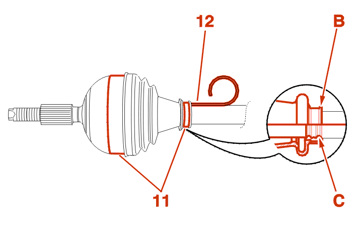
For driveshafts which do not have a positioning groove (C), Mark the position of the gaiter (B) .
Remove :
Remove as much of the old grease as possible .
IMPERATIVE : do not use solvents .
Fit a new gaiter .
Position the gaiter in relation to the mark made on removal or in its positioning groove .
Using a welding rod (12), allow air into the interior of the gaiter .
Remove the welding rod (12) .
Tighten the clip(s) (11) using the pliers [5] or [6] .