C7AP0UV1 - 406D9
FITTING ALARM
1 - PRESENTATION
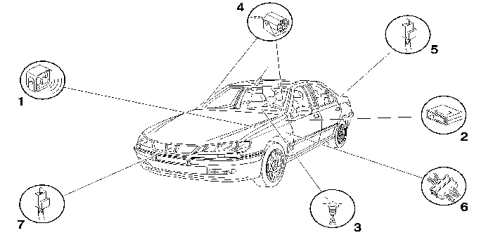
(1) Compact unit or siren .
(2) Alarm unit (modular system) .
(3) Display LED .
(4) Ultrasonic sensor .
(5) Luggage compartment switch .
(6) Built-in systems interface connection harness/Alarm .
(7) Bonnet switch .
2 - MODULAR ALARM : PART NO. 9671.ZG - 9671.ZH
2 - 1 - COMPOSITION
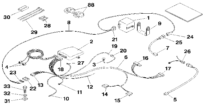
| reference | description | quantity |
|---|---|---|
| 1 | siren | 1 |
| 2 | alarm unit (modular system) | 1 |
| 3 | display LED | 1 |
| 4 | ultrasonic sensor (according to model) | 2 |
| 5 | luggage compartment switch | 1 |
| 6 | built-in systems interface connection harness/alarm | 1 |
| 7 | bonnet switch | 1 |
| 8 | siren harness | 1 |
| 9 | siren mounting plate | 1 |
| 10 | wire : red | 1 |
| 11 | earth terminal | 1 |
| 12 | wire : white/green | 1 |
| 13 | siren harness liaison connector | 1 |
| 14 | 26-way connector : mauve | 1 |
| 15 | 26-way connector : blue | 1 |
| 16 | 16-way connector : black (caliper) | 1 |
| 17 | 16-way connector : black | 1 |
| 18 | alarm unit connector | 1 |
| 19 | LED liaison connector | 1 |
| 20 | LED connector | 1 |
| 21 | siren liaison connector | 1 |
| 22 | siren harness connector | 1 |
| 23 | terminals | 5 |
| 24 | bonnet switch liaison connector | 1 |
| 25 | bonnet switch connector | 1 |
| 26 | luggage compartment switch harness | 1 |
| 27 | push button (according to specification) | 1 |
| 28 | fuse | 1 |
| 29 | clips | 3 |
| 30 | RAYCHEM sleeve | 2 |
| 31 | metal nut | 1 |
| 32 | washer | 1 |
| 33 | bolt(s) | 1 |
| 88 | remote control (according to specification) | 2 |
2 - 2 - WIRING DIAGRAM - MODULAR ALARM : PART NO. 9671.ZG
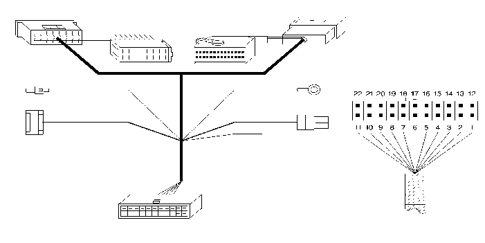
| terminal | function |
|---|---|
| 1 | door exterior protection information (appearance of earth on opening the doors) wire : white/black |
| 2 | bonnet exterior protection information (appearance of earth on opening the bonnet) wire : white/blue |
| 3 | luggage compartment exterior protection information (appearance of earth on opening the luggage compartment) wire : white/green |
| 4 | |
| 5 | |
| 6 | earth : black wire |
| 7 | |
| 8 | siren serial connection (frames) wire : blue/yellow |
| 9 | +LED (+ 12 V) wire : brown |
| 10 | ignition controlled +ve (+ 12V) wire : orange |
| 11 | battery +ve (+ 12V) wire : red |
| 12 | connected to track 15 wire : black |
| 13 | earth / wire : black |
| 14 | left door locking button information BSI side (appearance of earth door locked) wire : mauve |
| 15 | connected to track 12 wire : black |
| 16 | |
| 17 | left door locking button information door side (appearance of earth door locked) wire : grey |
| 18 | ancillaries output (+ 12 V / 500 mA) alarm set |
| 19 | |
| 20 | siren supply (+ 12 V / 4 A) wire : red |
| 21 | left direction indicator control output (+ 12 V) wire : yellow |
| 22 | right direction indicator control output (+ 12 V) wire : yellow |
2 - 3 - WIRING DIAGRAM / MODULAR ALARM : PART NO. 9671.ZG

| terminal | function |
|---|---|
| 1 | door exterior protection information (appearance of earth on opening the doors) wire : white/black |
| 2 | bonnet exterior protection information (appearance of earth on opening the bonnet) wire : white/blue |
| 3 | luggage compartment exterior protection information (appearance of earth on opening the luggage compartment) wire : white/green |
| 4 | |
| 5 | |
| 6 | earth : black wire |
| 7 | interior protection cut-off and configuration push button (appearance of earth on pressing) wire : yellow/green |
| 8 | siren serial connection (frames) wire : blue/yellow |
| 9 | + LED (+ 12V) wire : brown |
| 10 | ignition controlled +ve (+ 12V) wire : orange |
| 11 | battery +ve (+ 12V) wire : red |
| 12 | left door locking button information (appearance of earth door locked) wire : mauve |
| 13 | left direction indicator information (+ 12V) wire : yellow |
| 14 | |
| 15 | right door locking button information (appearance of earth door locked) wire : grey |
| 16 | unlocking motor power information wire : green |
| 17 | |
| 18 | battery +ve (+ 12V) wire : pink |
| 19 | |
| 20 | siren supply (+ 12V / 4A) wire : red |
| 21 | left direction indicator control output (+ 12V) wire : yellow |
| 22 | right direction indicator control output (+ 12V) wire : yellow |
3 - COMPACT ALARM : PART NO. 9671.ZJ
3 - 1 - COMPOSITION
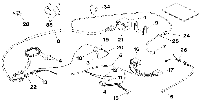
| reference | description | quantity |
|---|---|---|
| 1 | compact alarm | 1 |
| 3 | display LED | 1 |
| 4 | ultrasonic sensor | 2 |
| 5 | luggage compartment switch | 1 |
| 6 | built-in systems interface connection harness/alarm | 1 |
| 7 | bonnet switch | 1 |
| 8 | siren harness | 1 |
| 9 | siren mounting plate | 1 |
| 10 | wire : red | 1 |
| 11 | earth terminal | 1 |
| 12 | wire : blue | 1 |
| 13 | siren harness liaison connector | 1 |
| 14 | 26-way connector : mauve | 1 |
| 15 | 26-way connector : blue | 1 |
| 16 | 16-way connector : black (caliper) | 1 |
| 17 | 16-way connector : black | 1 |
| 19 | LED liaison connector | 1 |
| 20 | LED connector | 1 |
| 21 | siren liaison connector | 1 |
| 22 | siren harness connector | 1 |
| 24 | bonnet switch liaison connector | 1 |
| 25 | bonnet switch connector | 1 |
| 26 | luggage compartment switch harness | 1 |
| 28 | fuse | 1 |
| 34 | mounting cover | 1 |
| 88 | remote control | 2 |
3 - 2 - WIRING DIAGRAM
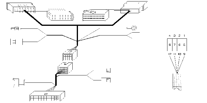
| terminal | function |
|---|---|
| 1 | battery +ve (+ 12 V) |
| 2 | switched earth LED |
| 3 | ignition controlled +ve (+ 12 V) |
| 4 | door exterior protection information (appearance of earth on opening the doors) |
| 5 | left door locking button information BSI side (appearance of earth door locked) |
| 6 | left door locking button information door side (appearance of earth door locked) |
| 7 | earth |
| 8 | left direction indicator control output (+ 12 V) |
| 9 | right direction indicator control output (+ 12 V) |
| 10 | luggage compartment exterior protection information (appearance of earth on opening the luggage compartment) |
| 11 | ancillaries output |
| 12 |
4 - FITTING
4 - 1 - VEHICLE PREPARATION
Open the bonnet .
Disconnect the battery + terminal .
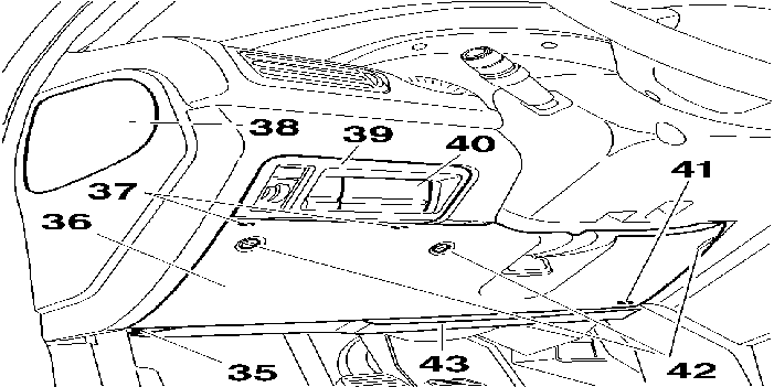
Remove the bolt (35) .
Unlock the button (42) 1/4 turn .
Tilt the fuse box lid (36) .
Remove :
Unclip the connections from the switches and buttons .
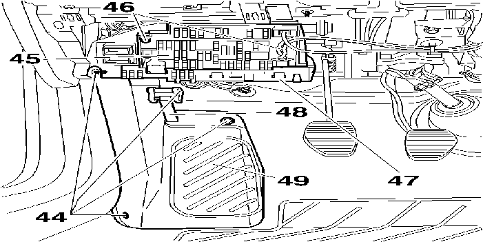
Remove :
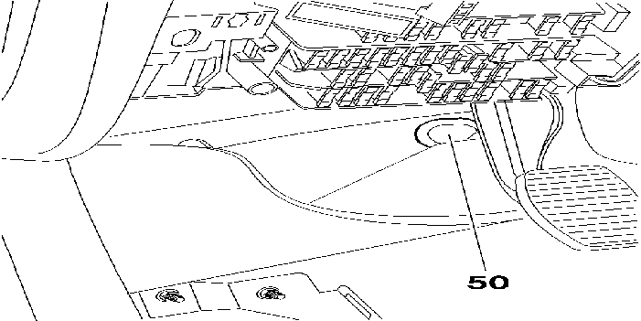
Partly move aside the carpet .
Remove : The rubber blank (50) .
4 - 2 - FITTING : SIREN (1) / BONNET SWITCH (7)
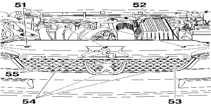
Remove :
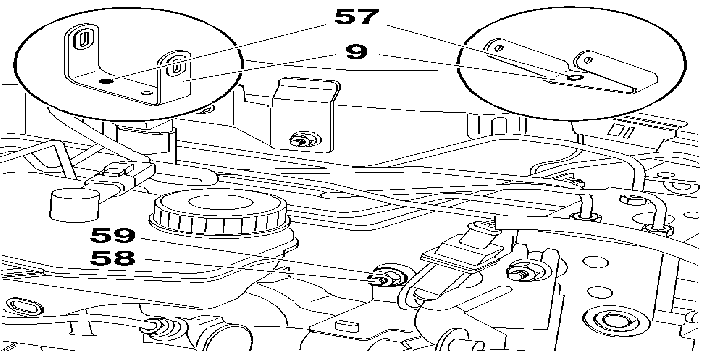
Enlarge the hole (57) of the siren mounting plate (9) to a diameter of 8 mm .
Remove the nut (59) from the original harness support .
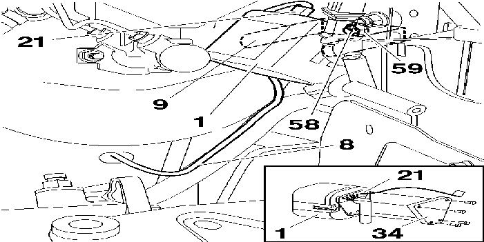
Secure the siren mounting plate (9) to the harness support bolt (58) using the nut (59) .
Connect the connector (21) for the siren harness (8) to the siren (1) .
Special feature of the compact alarm : Part No. 9671.ZJ :
Secure the siren (1) to the plate (9) .
Route the siren harness (8) along the original harness to the rubber blank hole (50) .
Pass the siren harness (8) through the rubber blank (50) .
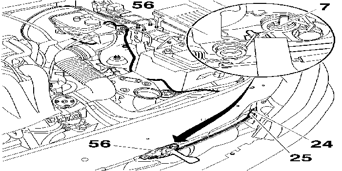
Route the bonnet switch connection connector wire (24) along the original harness to the battery tray, then to the left front light and clip it .
Clip the bonnet switch (7) to the lock (56) .
Clip the wire to the bonnet opening cable .
Connect the connector (25) to the connector (24) .
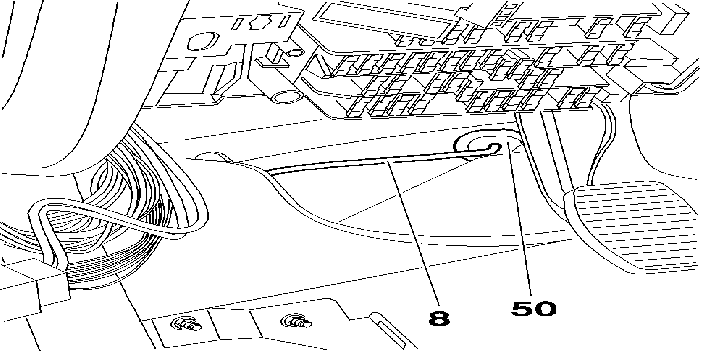
Pierce a hole in the rubber blank (50) using a 3 mm diameter punch .
Pass the siren harness (8) through the rubber blank (50) .
Fit the rubber blank (50) (ensure that it seals perfectly) .
LEFT HAND DRIVE
Shorten the siren harness to 1 metre from the rubber blank (50) .
Route the harness under the carpet towards the front left pillar then along the original harness to the passenger compartment fuse box (45) .
RIGHT HAND DRIVE
Route the harness under the carpet towards the front right pillar (under the fascia) along the original harness to the passenger compartment fuse box (45) .
ALL MODELS
4 - 3 - FITTING : BUILT-IN SYSTEMS INTERFACE CONNECTION HARNESS / (6) ALARM
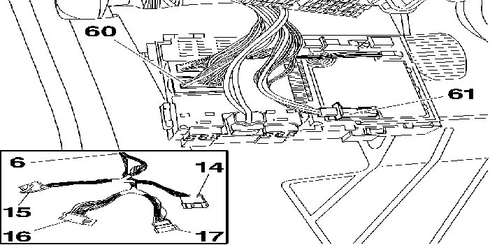
Disconnect the 26-way blue connector (61) and connect it to the 26-way purple connector (14) of the BSI/alarm harness (6) .
Disconnect the 16-way black connector (60) and connect it to the 16-way black connector (17) of the BSI/alarm harness (6) .
Connect the BSI/alarm harness connectors (15) and (16) to the BSI .
Clip the BSI/alarm harness (6) along the original harness .
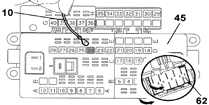
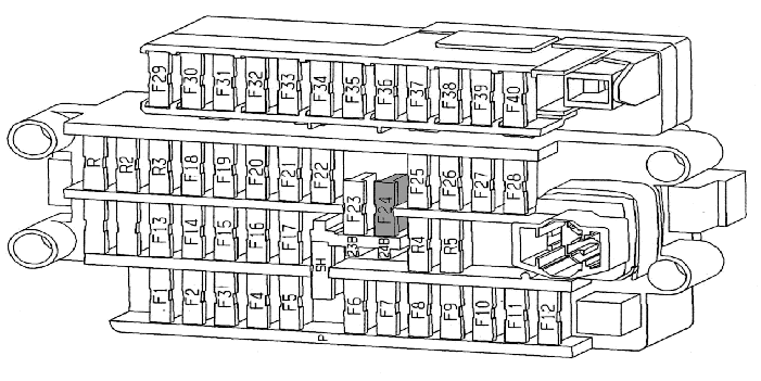
Remove :
Unclip the double catch (62) of the passenger compartment fuse box which corresponds to the fuses (22) - (11) - (12) .
Clip the terminal of the red wire (10) of the BSI/alarm harness (6) to the passenger compartment fuse box (45) at terminal 24 .
Reclip the double catch (62) .
Insert the fuse (28) (15 A) in position 24B .
Refit the fuses (22) - (23) - (25) previously removed .
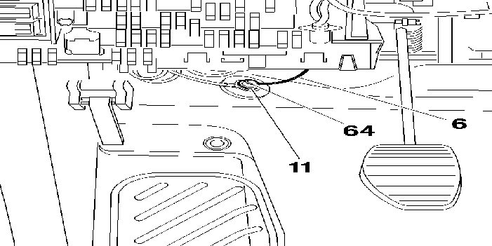
Secure the earth terminal (11) of the BSI/alarm harness (6) to the earth bolt (64) M009 .
4 - 4 - CONNECTION OF THE SIREN HARNESS (8) AND THE BUILT-IN SYSTEMS INTERFACE/ALARM HARNESS (6)
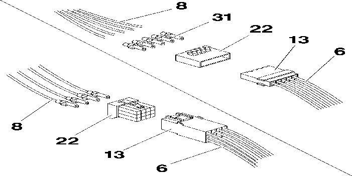
Special features of alarms Part Number 9671.ZH and 9671.ZG .
Strip the ends of the siren harness wires (8) .
Crimp the terminals (31) to the wires .
Special feature of the compact alarm : Part No. 9671.ZJ .
Remove the plastic end piece at the end of the siren harness (8) .
Insert the terminals in the siren harness switch (22) by matching the colours of the wires at the siren harness connection connector (13) of the BSI/alarm harness (6) .
Connect the connector (22) for the siren harness (8) to the BSI/alarm harness connector (13) .
4 - 5 - FITTING : DISPLAY LED (3)
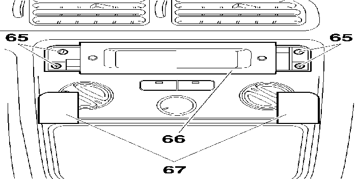
Remove :
Release the multi-function screen (66) (Pull outwards) .
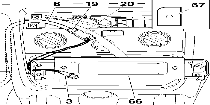
Special features of alarms Part Number 9671.ZH and 9671.ZG .
Route the wire of the LED connector (19) from the BSI/alarm harness (6) along the original harnesses to the multi-function screen .
Special feature of the compact alarm : Part No. 9671.ZJ .
Make a 10 mm diameter hole in the centre of the left-hand plastic blank (67) .
Pass the LED display wire (3) through the hole in the plastic blank (67) and clip the LED .
Pass the display LED (3) through the left-hand hole in the multi-function screen (66) .
Connect the connector (19) to the connector (20) of the display LED (3) and clip them to the multi-function screen .
Refit the multi-function screen (66) and the bolts (65) .
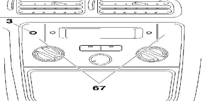
Special features of alarms Part Number 9671.ZH and 9671.ZG .
Make a 8 mm diameter hole in the centre of the left-hand plastic blank (67) .
Fit the display LED (3) on the plastic blank .
Refit the blanks (67) .
4 - 6 - FITTING : ULTRASONIC SENSOR (4) (ACCORDING TO SPECIFICATION)
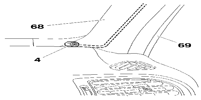
Partially unclip the door frame seal (69) (On both sides) .
Unclip the left and right hand windscreen pillars (68) .
Position the interior protection sensors (4) at the bottom of the windscreen pillars and secure them .
Route the wire of the right-hand sensor under the headlining to the left-hand sensor .
Route the sensor wires along the left-hand windscreen pillar to the passenger compartment fuse box (45) .
Special feature of the compact alarm : Part No. 9671.ZJ .
Connect the interior protection sensors to the siren harness (8) at the siren harness connector (22) observing the letters E and R .
4 - 7 - FITTING : LUGGAGE COMPARTMENT SWITCH (5)
4 DOOR SALOON COUPE
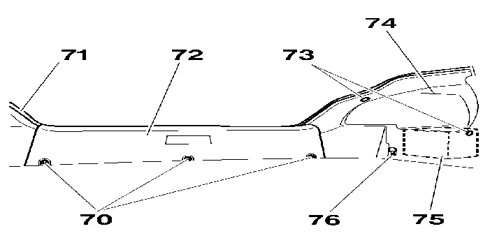
Partly unclip the frame seal (71) of the luggage compartment opening .
Remove :
Partly move aside the luggage compartment side trim (74) (Left-hand side) .
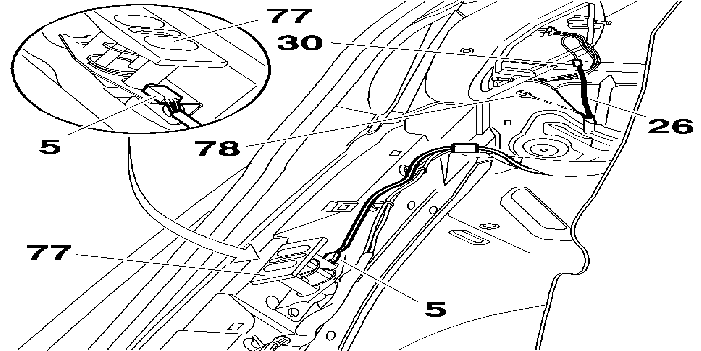
Fit the luggage compartment switch (5) to the striker (77) .
Connect the luggage compartment switch harness connector (26) to the luggage compartment switch (5) and clip the harness .
Secure the earth terminal of the luggage compartment switch harness (26) to the earth bolt (78) M054 .
Connect the luggage compartment switch harness (26) to the blue wire APV5 provided on the left rear light harness using the sleeve RAYCHEM (30) .
5 ESTATE
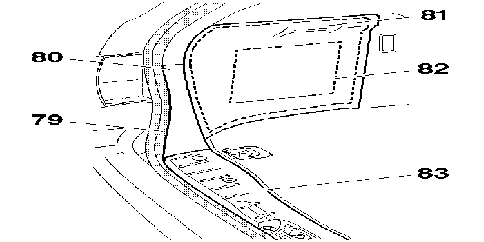
Partly unclip the frame seal (79) of the luggage compartment opening .
Remove :
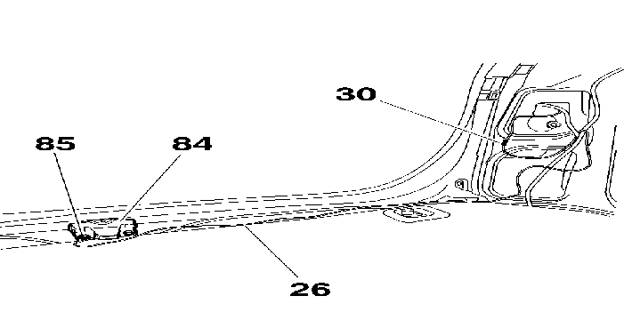
Mark the position of the luggage compartment striker (84) .
Remove the striker .
Fit the luggage compartment striker part number 872474 fitted with the luggage compartment switch .
Connect the luggage compartment switch harness connector (26) to the striker .
Secure the luggage compartment switch harness earth terminal (26) to the earth bolt (85) .
Connect the luggage compartment switch harness (26) to the blue wire APV5 provided on the left rear light harness using the sleeve RAYCHEM (30) .
ALL MODELS
Partly move aside the carpet .
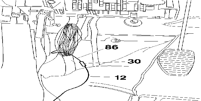
Connect the white/green or blue wire (12) (according to model) of the BSI/alarm harness to the blue wire APV5 (86) provided on the main harness at the front pillar using a Raychem sleeve (30) .
4 - 8 - FITTING : ALARM UNIT (2) (NUMBER 9671.ZG - 9671.ZH)
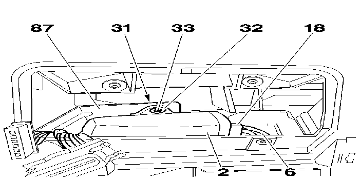
Connect the connector (18) for the BSI/alarm harness (6) to the unit (2) .
Remove the security card from the unit so that it can be given to the customer (According to specification) .
Connect the interior protection sensors to the central unit (according to model) observing the letters E and R .
Secure the central unit (2) to the metal crossmember (87) using the spire nut (31), the washer (32) and the bolt (33) .
Special feature of the compact alarm : Part No. 9671.ZH .
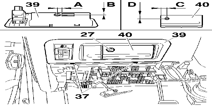
Make a 10 mm diameter hole on the switch support (39) to the left of the notch observing the dimensions A = 10 mm and B = 8 mm .
Make a 8 mm diameter hole on the left of the cover (40) observing the dimensions C = 12 mm and D = 13 mm .
Pass the push button (27) through the switch support .
Fit :
Secure the push button (27) to the diagnostic socket blank (40) .
Special features of alarms Part Number 9671.ZH and 9671.ZG .
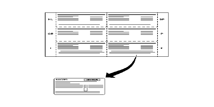
According to country, remove the sticker and attach it to the security card to be given to the customer .
5 - INITIALISATION (ALARM PART NUMBER 9671.ZH AND 9671.ZG)
5 - 1 - ALARM INITIALISATION : PART NO. 9671.ZH
The alarm control unit must be configured after fitting to be able to work with the vehicle's original remote control .
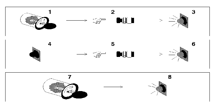
1 - Switch on the ignition .
2 - A pressure maintained for 20 seconds .
3 - After 10 seconds, the LED lights continuously .
4 - The LED goes out .
5 - 2 presses .
6 - The LED lights at each press .
7 - Switch off the ignition .
8 - The LED lights 2 times .
Initialisation is carried out .
NOTE : if the alarm control unit is not initialised, the alarm will not set on the first locking but when the original remote control button is pressed a second time with the locks bouncing .
Cancellation of the procedure in case of faulty manipulation .
To be able to re-initialise .

1 - Switch on the ignition .
2 - A pressure maintained for 20 seconds .
3 - After 10 seconds, the LED lights continuously .
4 - The LED goes out .
5 - 5 presses .
6 - The LED lights at each press .
7 - Switch off the ignition .
8 - The LED lights 5 times .
Again : Carry out the initialisation procedure (Refer to section 5.1 on) .
5 - 2 - INITIALISATION OF THE SIREN - ALARM : PART NO. 9671.ZH + PART NO. 9671.ZG
NOTE : the connection between the siren and the alarm control unit is a coded serial connection, it is therefore necessary to perform a learning procedure for the siren to work .
Alarm switched off .
Enter the emergency code shown on the card (Example : Confidential code) .
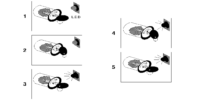
1 - Switch on the ignition .
2 - Quickly, switch off the ignition .
3 - Quickly, switch on the ignition again (in the case of example 43125, let the LED flash 4 times, as the first digit of the code is 4) .
4 - Switch off the ignition (The LED flashes rapidly) The indicators flash several times .
5 - Switch on the ignition again (In the case of example 43125, let the LED flash 3 times, as the second digit of the code is 3) .
Repeat the operation up to the fifth digit .
Acceptance of the code confirmed by several flashes of the indicators .
Switch on ignition for 10 seconds (the LED shines continuously for 20 seconds) .
Switch off the ignition .
Initialisation is carried out .
6 - REFITTING THE COMPONENTS
Proceed in the reverse order to removal .
Check the correct electrical operation of the equipment .
NOTE : notice valid subject to product modification .