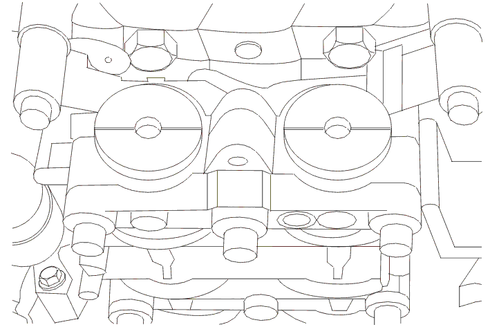
B1EE0BK1 - 607 EW12J4 ENGINE
CHECKS AND ADJUSTMENTS BALANCING SHAFTS HOUSING
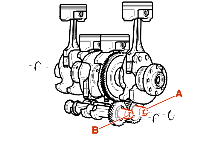
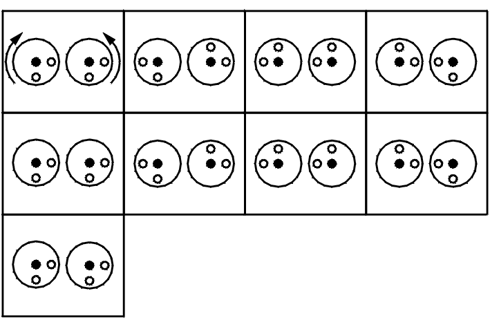
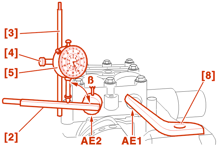
(A) Counter-rotating shaft AE1 (driven by the crankshaft) .
(B) Rotating shaft AE2 (driven by the counter-rotating shaft) .
1 - SPECIAL TOOLS
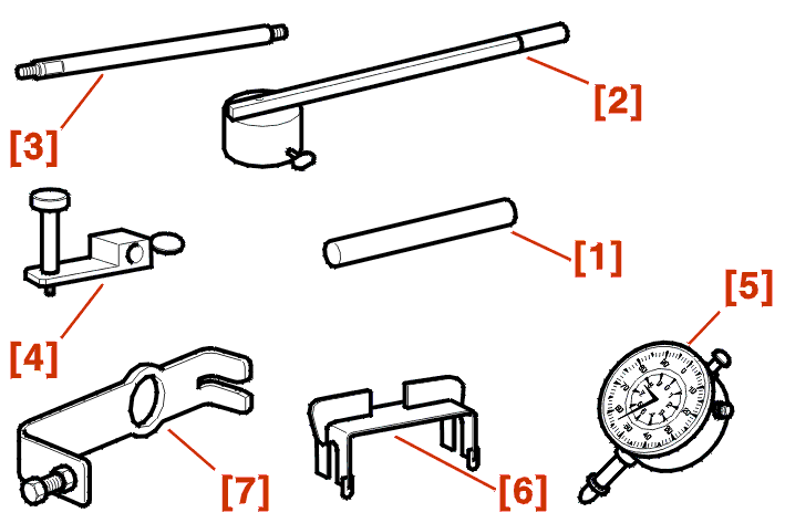
[1] crankshaft setting rod (-).0189-B .
[2] Rule for checking the balancing shafts clearance (-).0190-A .
[3] Dial gauge support (-).0190-C1 .
[4] Dial gauge support (-).0190-C2 .
[5] dial gauge (-).1504 .
[6] Balancing shafts positioning gauges (-).0190-D .
[7] Balancing shafts positioning gauge clamp (-).0190-E1 .
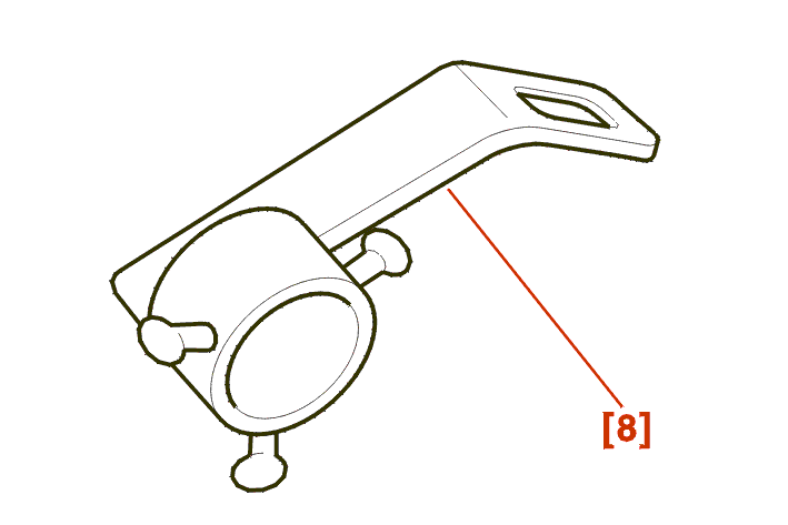
[8] Balancing shaft immobilisation lever (-).0190-F1 .
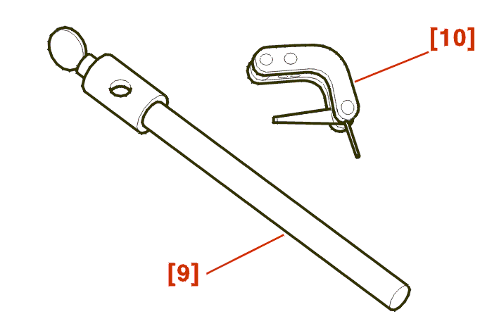
[9] Support rod (-).0504-A1Z .
[10] Dial gauge transfer mechanism (-).0117-AG .
2 - VISUAL CHECK BALANCING SHAFT CONDITION
remove the sump .
Clean the teeth of the crankshaft crown wheel and the balancing shaft pinions .
Spray brake cleaning product onto the teeth, turning the engine manually .
Dry the teeth using compressed air .
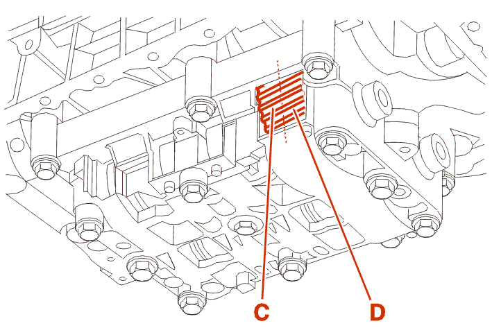
C : Section of the teeth in contact with the crankshaft .
D : Section of the teeth in contact with the rotating shaft pinion .
| C (*) | D (*) | operation(s) to be carried out |
|---|---|---|
| correct | correct | carry out an axial check of the balancing shafts |
| damaged | correct | replace the crankshaft and the balancing shaft housing |
| correct | damaged | replace the balancing shaft housing |
| damaged | damaged | replace the crankshaft and the balancing shaft housing |
| (*) condition of the teeth | ||
3 - CHECK AXIAL CLEARANCE
3 - 1 - SETTING UP THE TOOLS
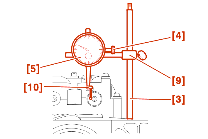
Screw the tool [3] onto the cylinder block .
Prepare the assembly [5] - [4] - [9] - [10] and fit it on the tool [3] .
3 - 2 - MEASUREMENT
Place the balancing shaft at the axial clearance limit .
Set the dial gauge to zero .
Turn the balancing shaft axially and read the clearance value .
If the value is incorrect ; Replace the balancing shaft housing .
If the value is correct ; Carry out the same check on the second balancing shaft .
If the value is correct ; Check the clearance between the crankshaft and the balancing shaft AE1 .
4 - CHECKS AND ADJUSTMENTS TOOTH CLEARANCE BETWEEN THE CRANKSHAFT AND THE COUNTER-ROTATING BALANCING SHAFT (AE1)
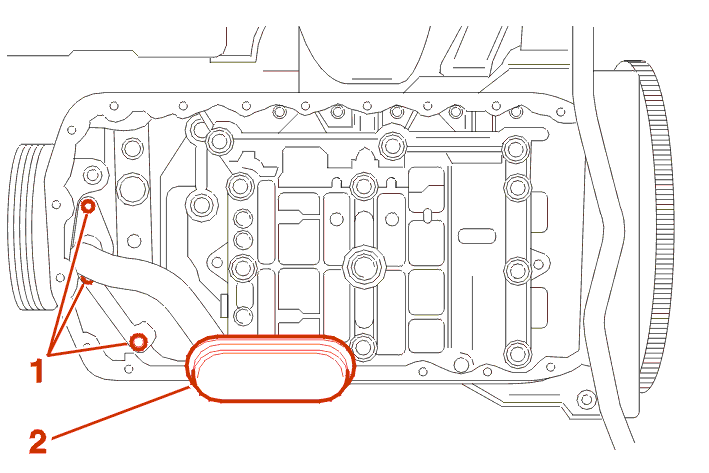
Remove The bolts (1) .
Screen (2) with its seal .
Move the engine to the setting point .
4 - 1 - SETTING UP THE TOOLS
Screw the tool [3] onto the cylinder block .
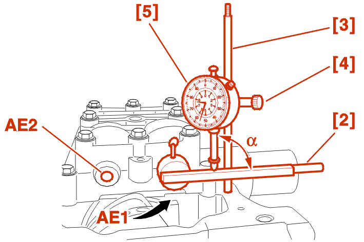
Fit the tool [2] on the balancing shaft AE1 .
Prepare the checking assembly [4] - [5] .
Fit the assembly [4] - [5] so that the dial gauge contact needle [5] forms an angle of 90° with the tool [2] .
4 - 2 - OPERATING CLEARANCE MEASUREMENT
IMPERATIVE : when each measurement is taken, block axial movement of the balancing shaft AE1 by pressing on it with your hand .
Press the end of the tool (2) to bring it to its limit (moderate force) .
Set the dial gauge to zero .
Press the end of the tool [2] from limit to limit to measure the tooth clearance between the crankshaft crown wheel and the balancing shaft AE1 .
This measurement must be taken 9 times every 90 ° of the balancing shaft to carry out one complete revolution of the crankshaft .
As the 1st and 9 measurement points are the same, if too great a difference is detected, repeat a series of measurements .
IMPERATIVE : the clearance value must be between 1/100 and 7/100 .
If the value is incorrect : Check the clearance between the balancing shafts AE1 and AE2 ; Check the clearance between the crankshaft and the shaft AE1 .
If the value is correct : Check the clearance between the balancing shafts AE1 and AE2 .
4 - 3 - ADJUSTMENT
Peg the crankshaft (Using the tool [1]) .
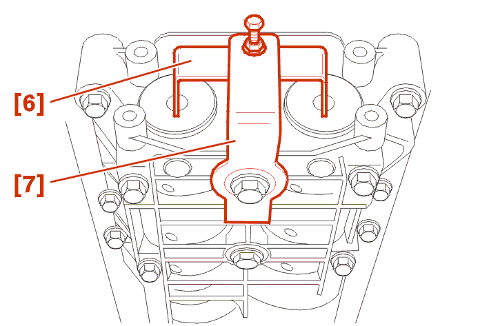
Position the tools [6] - [7] .
Remove :
Fit :
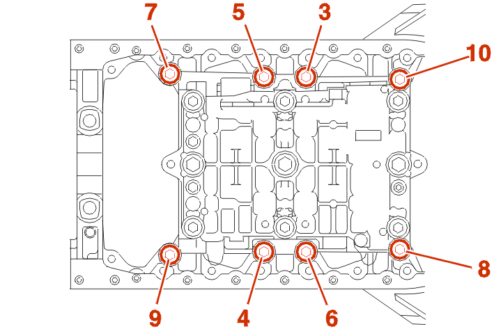
Tighten the bolts (3) - (4) - (5) - (6) - (7) - (8) - (9) - (10) to 2.2 daN.m (In order) .
Remove the tools [6] - [7] .
Check the clearance between the crankshaft and the balancing shaft AE1 .
Retain the lowest clearance value and, in line with the table below, use it to identify the value of the shim for the final assembly .
| minimum clearance | thickness of shim(s) to be fitted | shim mark(s) |
|---|---|---|
| 0,07 | 1,47 | 47 |
| 0,08 | 1,47 | 47 |
| 0,09 | 1,45 | 45 |
| 0,1 | 1,43 | 43 |
| 0,11 | 1,41 | 41 |
| 0,12 | 1,41 | 41 |
| 0,13 | 1,39 | 39 |
| 0,14 | 1,37 | 37 |
| 0,15 | 1,35 | 35 |
| 0,16 | 1,35 | 35 |
| 0,17 | 1,33 | 33 |
| 0,18 | 1,31 | 31 |
| 0,19 | 1,29 | 29 |
| 0,2 | 1,29 | 29 |
| 0,21 | 1,27 | 27 |
| 0,22 | 1,25 | 25 |
| 0,23 | 1,23 | 23 |
| 0,24 | 1,23 | 23 |
| 0,25 | 1,21 | 21 |
| 0,26 | 1,19 | 19 |
Refit the tools [6] - [7] .
Remove :
Fit :
Tighten the bolts (3) - (4) - (5) - (6) - (7) - (8) - (9) - (10) to 2.2 daN.m (In order) .
Remove the tools [6] - [7] .
Check the clearance between the crankshaft and the balancing shaft AE1 .
If the value is incorrect : Repeat the clearance adjustment operation .

Fit :
fit the sump .
5 - CHECK TOOTH CLEARANCE BETWEEN THE COUNTER-ROTATING BALANCING SHAFT (AE1) AND THE ROTATING BALANCING SHAFT (AE2)
Peg the crankshaft ( Using the tool [1]) .
5 - 1 - SETTING UP THE TOOLS
Screw the tool [3] onto the cylinder block .
Fit the tool [8] on the balancing shaft AE1 and secure it on the cylinder block .
Fit the tool [2] on the balancing shaft AE2 .
Prepare the checking assembly [4] - [5] .
Fit the assembly [4] - [5] so that the dial gauge contact needle [5] forms an angle of 90° with the tool [2] .
5 - 2 - OPERATING CLEARANCE MEASUREMENT
Press the end of the tool (2) to bring it to its limit (moderate force) .
Set the dial gauge to zero .
Press the end of the tool [2] from limit to limit to measure the tooth clearance between the crankshaft crown wheel and the balancing shaft AE1 - AE2 .
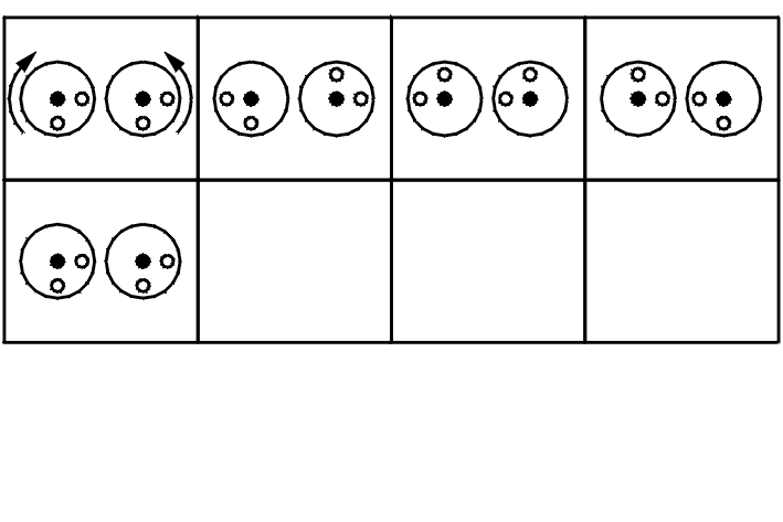
This measurement must be taken 5 times every 90 ° of the balancing shaft to carry out one complete revolution of the crankshaft .
As the 1st and 5 measurement points are the same, if too great a difference is detected, repeat a series of measurements .
IMPERATIVE : the clearance value must be between 1/100 and 7/100 .
If the value is incorrect : Replace the balancing shaft housing .
Fit :
fit the sump .