B1BS00K1 - 406D9 DW10 ENGINE
DISMANTLING - DISMANTLING ENGINE
1 - DISMANTLING - DISMANTLING
Unclip the engine harness, then disconnect it from the various sensors .
Remove :
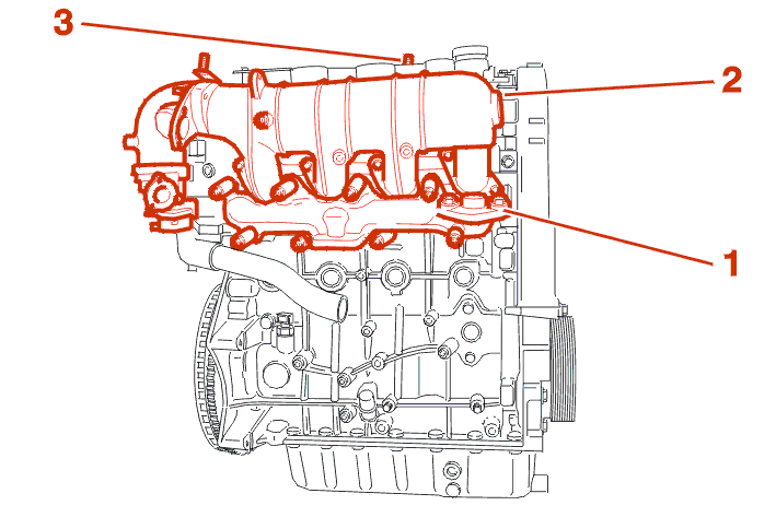
Remove :
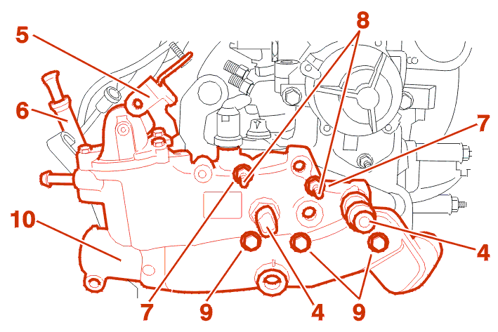
Disconnect the connectors (4) .
Remove :
Secure the engine on a stand .
Remove : The thermostat (10) .
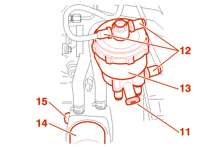
Place a draining tray under the engine .
Open the bleed screw (11) .
IMPERATIVE : WHEN WORKING ON THE DIESEL CIRCUIT, FOLLOW THE ADVICE ON CLEANLINESS .
Move aside the connections (12) .
IMPERATIVE : PLUG THE HOLES USING TOOL [1U] .
Remove :
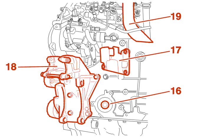
Remove :
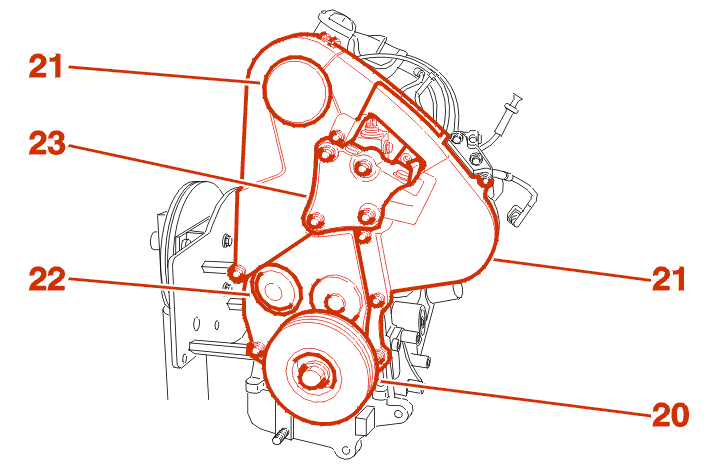
LOCK THE FLYWHEEL WITH THE STOP [1I] .
Remove :
Remove the starter .
1 - 1 - 1ST FITTING : WITH SINGLE ENGINE FLYWHEEL
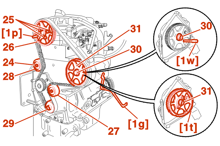
PEG THE FLYWHEEL USING THE ROD [1G] .
1 - 2 - 2ND FITTING : WITH DOUBLE ENGINE FLYWHEEL
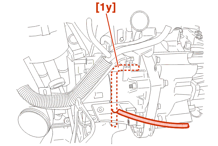
peg the flywheel using the rod [1y] .
Peg :
Slacken the bolt (24) .
Remove the timing belt .
Slacken the bolts (25) .
Remove :
Pin the pulley (31) USING THE TOOL [1W] .
Slacken the nut (30) .
Remove the high pressure pump drive pulley (31) (USING THE TOOL [1T]) .
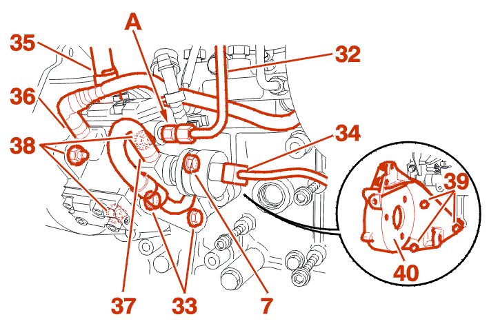
IMPERATIVE : CLEAN THE FUEL UNIONS BEFORE SLACKENING .
IMPERATIVE : apply a counter-torque at (A) .
Remove :
Disconnect the connectors (34), (35) .
Move aside : The hoses (36) and (37) .
PLUG THE HOLES USING TOOL [1U] .
Remove the fastenings (38) .
Remove the high pressure fuel pump .
NOTE : if necessary : entrust the checking of the high pressure injection pump to a dealer .
Remove :
IMPERATIVE : WHEN WORKING ON THE DIESEL CIRCUIT, FOLLOW THE ADVICE ON CLEANLINESS .
WARNING : if any work is carried out on the high pressure pipes they must always be replaced .
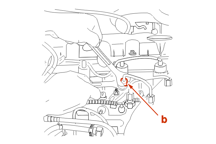
Apply a counter-torque at (b) .
Slacken the unions .
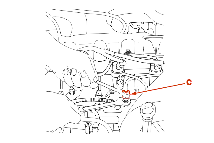
Apply a counter-torque at (c) .
Slacken the unions on the high pressure fuel direct injection rail .
Remove : The 4 high pressure pipes .
IMPERATIVE : plug the openings, USING THE TOOL [1U] .
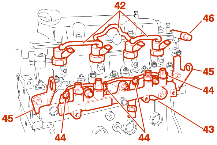
Remove :
Plug the openings, USING THE TOOL [1U] .
Remove :
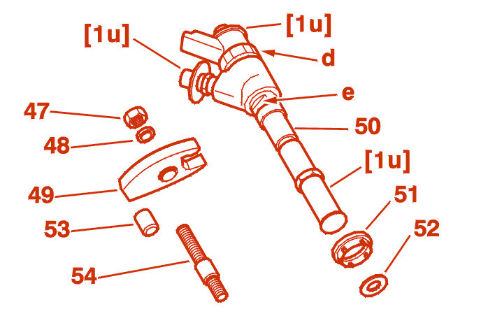
IMPERATIVE : do not turn the nut (d) .
Remove :
NOTE : if the injector cannot be removed, remove the stud (54) by using a lock-nut, then, using an open ended spanner, turn the injector at (e) .
IMPERATIVE : close the injector holes, plug the openings (USING THE TOOL [1U]) .
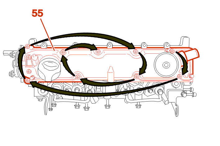
Remove :
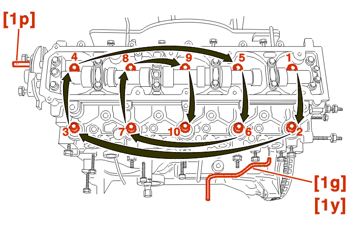
SLACKEN THE CYLINDER HEAD BOLTS IN THE ORDER INDICATED, USING THE TOOL [4] .
Remove the cylinder head bolts .
ROCK AND FREE THE CYLINDER HEAD USING LEVERS [1N] .
Remove the cylinder head and gasket .
Clean the threads and taps .
REMOVE THE TOOL [1G] OR [1Y] .
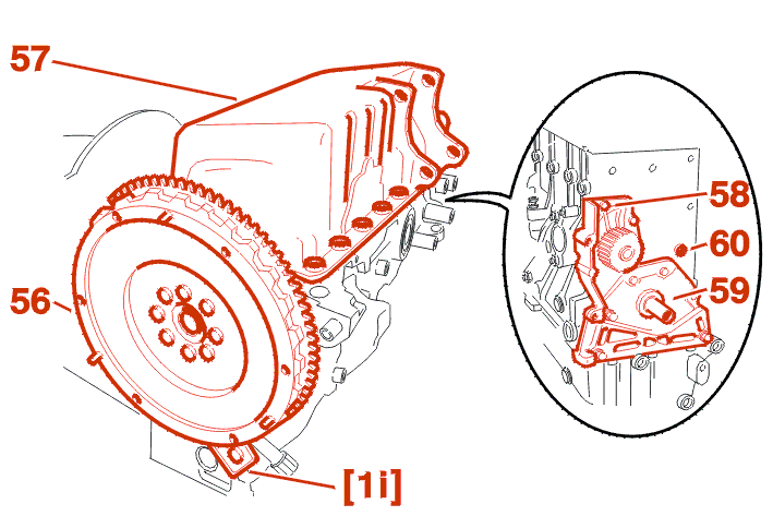
INSERT THE FLYWHEEL STOP [1I] .
Remove :
WARNING : take care not to distort the mating surface .
Remove :
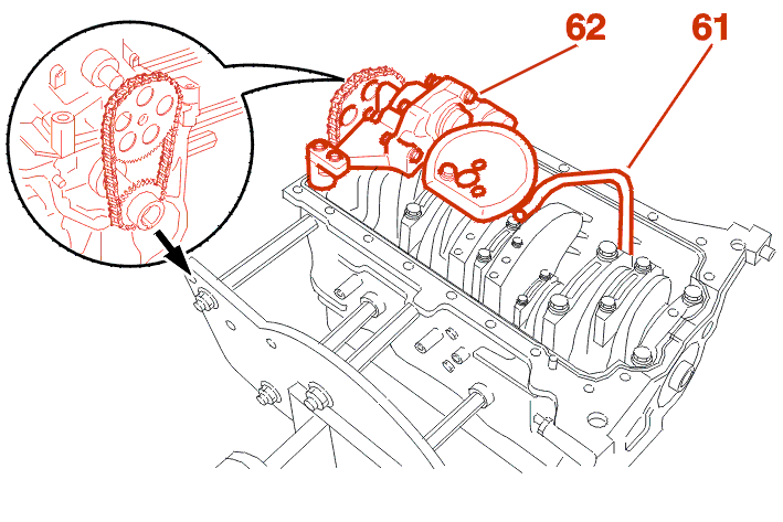
Remove :
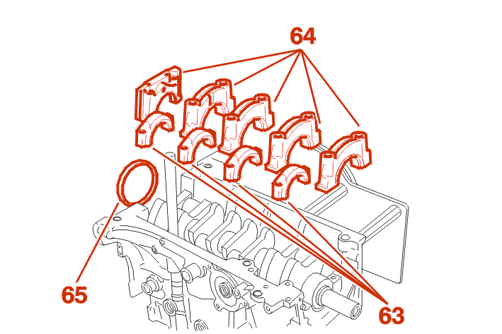
IMPERATIVE : mark the location of the big end caps and main bearings .
Remove :
Recover the end float adjusting shims on the main bearing (no. 2) .
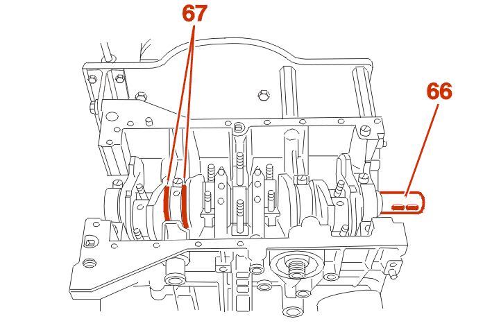
IMPERATIVE : mark the location of the main bearing half shells .
Remove :
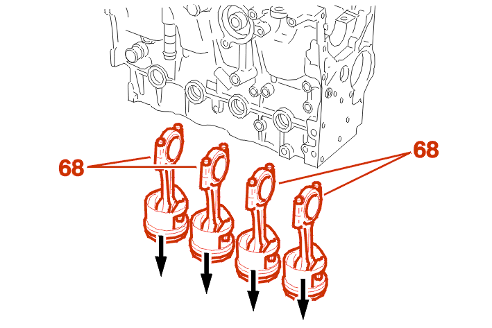
Remove :
Fit :
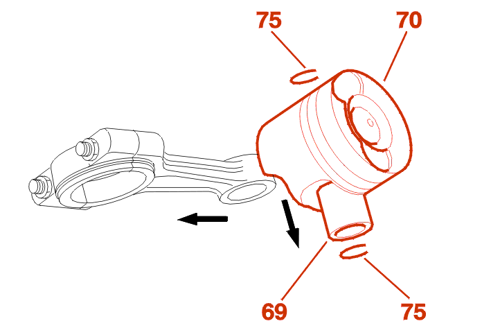
Remove :
NOTE : the gudgeon pins are paired with the pistons, do not mix the components .
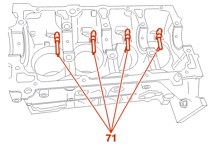
Remove the piston head jets (71) .
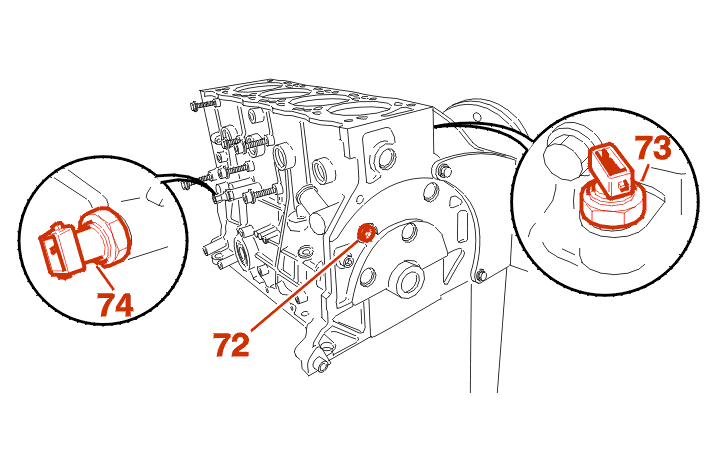
Remove :