B1BG1GK1 - 406D9 ES9J4S ENGINE
REMOVAL - REFITTING POWER UNIT
1 - SPECIAL TOOLS
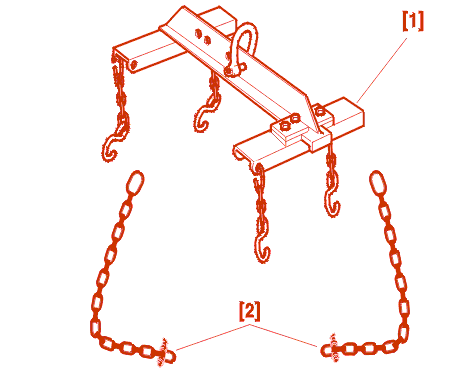
[1] Cross beam (-).0135 A .
[2] Lifting chain (-).0102 M .
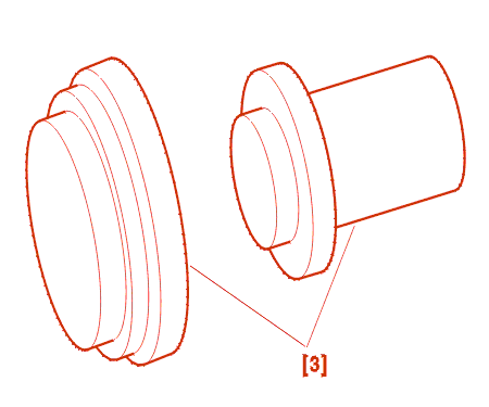
[3] final drive output oil seal fitting drifts (-).0332 A (-).0332 B .
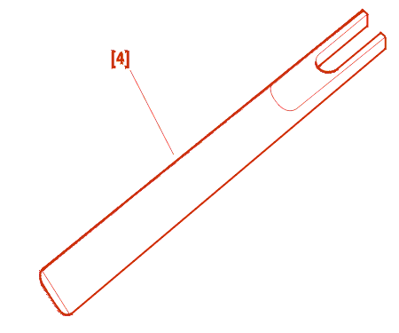
[4] Tool for unclipping 10 dia. ball joints (-).0216 G1 .
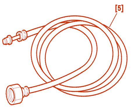
[5] Pipe with adapter for valve SHRADER (-).0141-T1 .
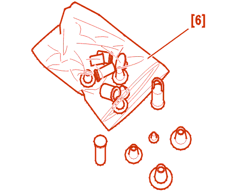
[6] Set of plugs (-).0188-T .
2 - REMOVAL
The power unit is removed from above .
Place the bonnet in the parking position .
Remove :
Disconnect the battery .
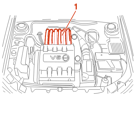
REMOVE THE INLET MANIFOLD (1) .
Remove :
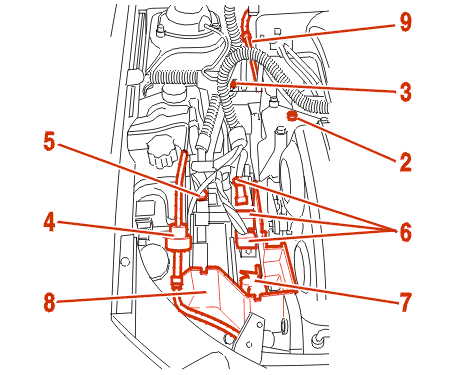
Disconnect the pipe and the canister connector (4) .
Disconnect the double relay connector (5) .
Disconnect the connectors (6) from the ecu (7) .
Remove the control unit (7) .
Remove the tray (8) .
Move aside the harnesses .
Lower the fuel pressure by connecting the end of the tool [5] to the valve SCHRADER; catch the fuel in a receptacle .
Move aside the pipe (9) .
REMOVE THE ANCILLARY DRIVE BELT .
Remove :
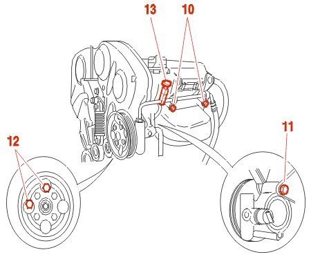
Disconnect the connector (13) from the power steering circuit pressure sensor .
Move aside the power steering pump .
Remove :
Drain :
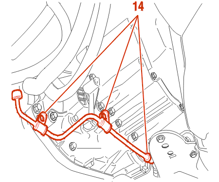
Unclip the power steering pipe (14) .
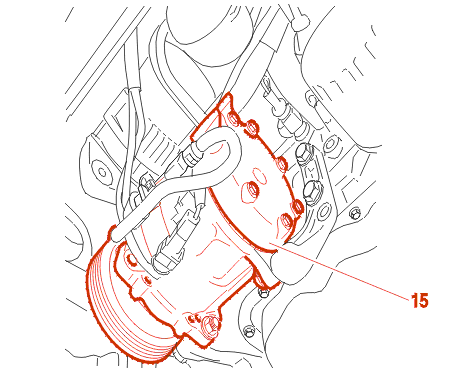
Disconnect the compressor electrical supply .
Unclamp the air conditioning pipe .
Move aside the air conditioning compressor (15) with its securing bracket without opening the fluid circuit .
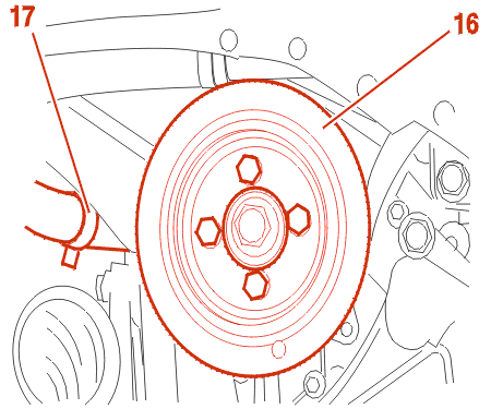
Remove the crankshaft pulley (16) .
Move aside the coolant hose (17), engine side .
REMOVE FRONT AND REAR PRECATALYTIC CONVERTERS .
Remove the lower torque reaction rod .
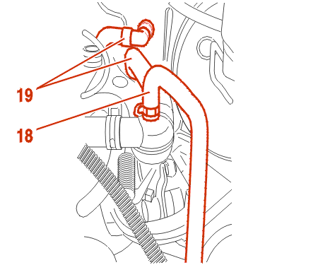
Disconnect the pipe (18) and move it aside .
Disconnect the heat matrix connectors (19) .
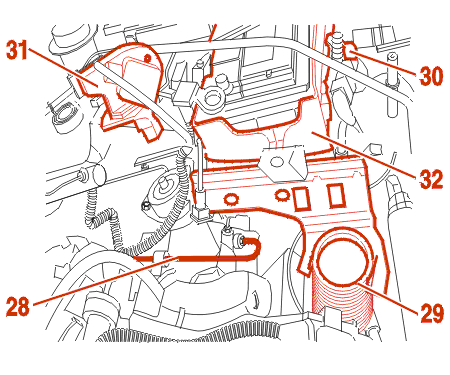
Disconnect the clutch control pipe (28) .
IMPERATIVE : protect the ends of the pipe and the clutch slave cylinder using the tools [6] .
Remove :
Move aside :
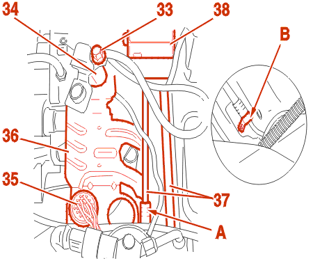
Remove the nut (33) .
Disconnect the connectors (34)-(35) .
Loosen the base of the connector (35) on its support (36) .
Move aside the bracket (36) .
Unclamp the pipes (37) At (A)-(B) .
Move aside the anti-lock unit (38), taking care not to damage the rigid pipes .
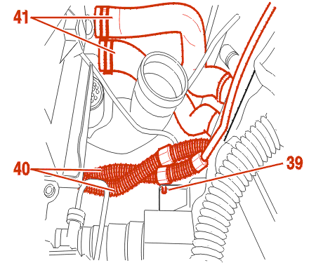
Remove the bolt (39) .
Unclamp and move aside the harnesses (40) .
Disconnect the pipes (41) .
Remove the radiator .
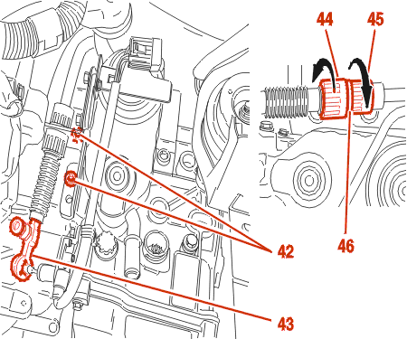
Remove the 2 mounting bolts (42) on the gearbox control cable adjustment bracket .
Unclip the link (43) .
Separate control cable take-up support by turning rings (44) and (45) in direction indicated, push ring (46) back into place .
Move aside The control cable .
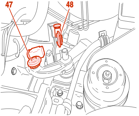
Using the tool [4], unclip the swivel joints (47) - (48) .
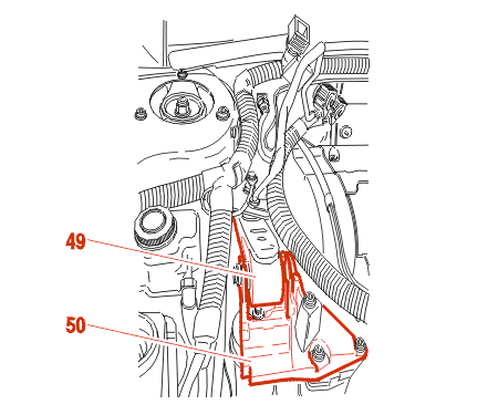
Remove :
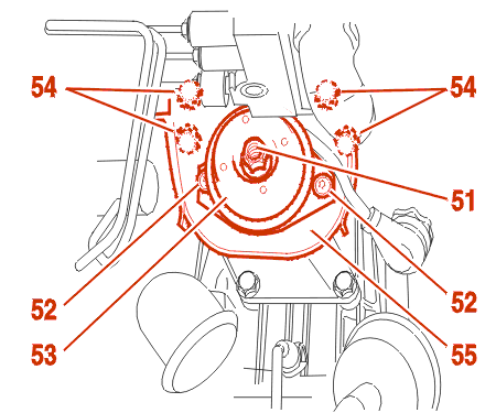
Remove :
3 - REFITTING
Always renew :
Lower the power unit .

Fit :
Position the power train .
Fit :
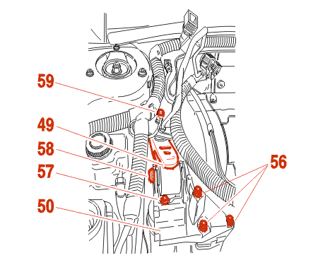
Fit :
Lower the power train on to its mountings .
Tighten :
Remove the tools .
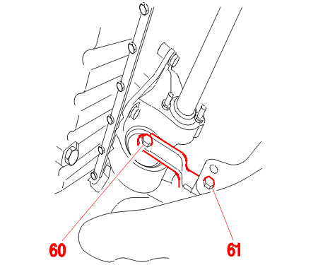
Fit the bottom engine mounting torque reaction rod .
Tighten :
Tighten the drive shaft nuts to 24.5 m.daN .